Continue to Site

Welcome to our site!

Electro Tech is an online community (with over 170,000 members) who enjoy talking about and building electronic circuits, projects and gadgets. To participate you need to register. Registration is free. Click here to register now.

  • Welcome to our site! Electro Tech is an online community (with over 170,000 members) who enjoy talking about and building electronic circuits, projects and gadgets. To participate you need to register. Registration is free. Click here to register now.

5vdc to 12vdc converter assistance

Status
Not open for further replies.

qsiguy

Member
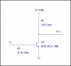
I have a device that has a 5 vdc square wave pulsed output that I need to step up to a 12 vdc output that retains the original pulse frequency. Current requirement is very low. Can someone post a circuit to accomplish this or offer some suggestions to get me started? I have CircuitMaker and have been experimenting with some circuits but I'm not having much luck.

Thanks in advance for any help!
 
They are IR pulses for a tv remote control so they vary from around 30kHz-50kHz I believe. I need to measure a few samples with the o-scope to verify but I'm sure it will need to operate approximately in that range.

Can I just use a simple op amp circuit or will they switch fast enough?
 
Last edited:
They are IR pulses for a tv remote control so they vary from around 30kHz-50kHz I believe. I need to measure a few samples with the o-scope to verify but I'm sure it will need to operate approximately in that range.

Can I just use a simple op amp circuit or will they switch fast enough?

All you should need is something like the attached. Actually any NPN switching transistor or logic level MOSFET would work. As long as the frequency is within the the transistors range. You may need to lower R2's value.

Ron
 

Attachments

  • Trans Amp.png
    Trans Amp.png
    5.9 KB · Views: 397
Thank you. That's pretty much what I've been experimenting with. One issue I may have with this circuit is that when the 5v input is high the output is low and vice versa. The issue I was having with using an op amp is that it never went down to 0v when the input was off, it stayed at around 800-900 mV.

Thoughts?
 
I'm kind of surprised at Reload-Ron, since he gave you an inverting amplifier. You could turn it into a non-inverting one by making it an emitter follower (take the output from the emitter rather than the collector), which give an in-phase output.
 
I'm kind of surprised at Reload-Ron, since he gave you an inverting amplifier. You could turn it into a non-inverting one by making it an emitter follower (take the output from the emitter rather than the collector), which give an in-phase output.

I'm kind of surprised about you. :eek:

The OP wants an output higher than the input.

An emitter follower requires VDD + 0.6V to put out VDD. If the collector voltage is +12V and the base voltage is +5V the output voltage is about +3.5V.

Better use two inverters in case the output signal must have the same phase as the input signal.

Take a look. It works.
 

Attachments

  • LEVEL-ADAPTER-0.gif
    LEVEL-ADAPTER-0.gif
    7.6 KB · Views: 256
  • LEVEL-ADAPTER-1.gif
    LEVEL-ADAPTER-1.gif
    7.4 KB · Views: 396
Ya know what peoples, I sure as hell did that! :)

I never gave it much thought, just threw a transistor out there. Hell, I'm surprised at me too.

Thanks Hans and hope things are going well in your corner of the planet.

Thanks Carbonzit.

Ron
 
Thanks guys. Looks like this should work, I'll get it on the breadboard and see how it does. I've looked at Mouser and Digikey and don't see a "BC547BP" exactly. I found the BC547B and other variants but not that specific #. Do I need to find the "..BP" type or will the others work fine?
 
You're quite welcome, "Reload", even though I screwed up on my suggestion (emitter follower).

So to summarize, what the O.P. needs is a simple noninverting amplifier with a gain of 2.4, correct? (5V--> 12V) and a bandwidth of 50kHz..

How can this be implemented with two transistors? Anyone care to show us? (Unfortunately, my electronic circuit design skills are not quite up to the task, which is why I ask, for my benefit as well.)
 
Thanks guys. Looks like this should work, I'll get it on the breadboard and see how it does. I've looked at Mouser and Digikey and don't see a "BC547BP" exactly. I found the BC547B and other variants but not that specific #. Do I need to find the "..BP" type or will the others work fine?

Any BC547 will work just fine. They have slightly different parameters, but for the purposes of your circuit they'll behave almost identically.

If you buy them from Jameco, I think they're about 7 cents each.
 
Status
Not open for further replies.

Latest threads

New Articles From Microcontroller Tips

Back
Top