Continue to Site

Welcome to our site!

Electro Tech is an online community (with over 170,000 members) who enjoy talking about and building electronic circuits, projects and gadgets. To participate you need to register. Registration is free. Click here to register now.

  • Welcome to our site! Electro Tech is an online community (with over 170,000 members) who enjoy talking about and building electronic circuits, projects and gadgets. To participate you need to register. Registration is free. Click here to register now.

5v/12vdc inputs and only one of those as outputs using PIC18fxxxx

Status
Not open for further replies.

StealthRT

Member
Hey all I am trying to find an IC that can accommodate having 2 inputs but only one output depending on what I send via a PIC18fxxxx micro controller. This sounds like it would be a DPST but I can't really find anything like that I can control from a PIC to choose what output needs to be on.

The 5vdc and 12vdc will be to power a PC FAN. The 5 and 12vdc will be coming from the PC PSU.

A 12vdc fan is around 0.25A ~4W
A 5vdc fan is around 0.18A ~2W

So something like so:
Code:
                    |------|
    ---5vdc-in----->|  IC  |
    ---12vdc-in---->|  ?   |-----5 or 12vdc-out-->
    ---PIC pin-in-->|      |
                    |------|
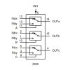
Or better visually is this:
i9oGV.jpg


The PIC pin would control the IC to let it know which voltage to output.

Does anyone know if this type of IC exists? I'll need to be able to do 10 outputs all together.
 
Not at 1/4 amp, or at least not for very long. Does it have to be a single component, or will two optocouplers work?

ak
 
how would the HEF4053B look for my scenario?

I'll have to have a total of 10 outputs so that would be a lot of optos
 
so with my attached image would this be correct for the 4053 IC?:

- 11 goes to PIC pin.
- 10 goes to PIC pin.
- 9 goes to PIC pin.
- 12 would be the 5vdc IN.
- 2 would be the 5vdc IN.
- 5 would be the 5vdc IN.
- 13 would be the 12vdc IN.
- 1 would be the 12vdc IN.
- 3 would be the 12vdc IN.
- 14 would be either 5 or 12vdc OUTPUT depending on PIC pin signal.
- 15 would be either 5 or 12vdc OUTPUT depending on PIC pin signal.
- 4 would be either 5 or 12vdc OUTPUT depending on PIC pin signal.

that correct?
 

Attachments

  • suiche-y-multiplexor-analogo-4053b.jpg
    suiche-y-multiplexor-analogo-4053b.jpg
    25.2 KB · Views: 240
so with my attached image would this be correct for the 4053 IC?:

- 11 goes to PIC pin.
- 10 goes to PIC pin.
- 9 goes to PIC pin.
- 12 would be the 5vdc IN.
- 2 would be the 5vdc IN.
- 5 would be the 5vdc IN.
- 13 would be the 12vdc IN.
- 1 would be the 12vdc IN.
- 3 would be the 12vdc IN.
- 14 would be either 5 or 12vdc OUTPUT depending on PIC pin signal.
- 15 would be either 5 or 12vdc OUTPUT depending on PIC pin signal.
- 4 would be either 5 or 12vdc OUTPUT depending on PIC pin signal.

that correct?


maybe you didn't read AK's response ??
 
The 4053, or any other standard CD4xxx multiplexer, will not work in this application. Two things. First, the absolute minimum ON resistance is 125 ohms. To push 1/4 amp through that would take over 31 volts. With a 12 V source, the short circuit current at the output would be less than 1/10 amp. Second, the absolute max current in any pin is 10 mA.

per
the
datasheet

ak
 
Hi SRT,

May I suggest that you rethink the fan control.

If you would consider this we can probably suggest a better approach.:)

spec

PS: please fill in 'Location' on your user page.
 
The circuit below gives an idea of the type of circuit I am thinking about to control the fans.

On the other hand, you could use pulse width modulation and just the 12V supply. In that case only a single control line would be required from the microcontroller. and the circuit would be reduced to about four components.

spec

2016_10_28_iss01_ETO_PC_FAN_CONTROLLER_VER1.png
 
Last edited:
Nice, AK :)
 
This is another suggestion using discreet components.
CO_switch.jpg


This is one changeover switch function. I suggest a schottky diode such as a 1N5818 and a P channel mosfet such as an NDS356. The diode would have a forward voltage drop of about 0.5 volts So the out put when 5 volts was selected would only be about 4.5 volts. A high level on the control input selects 12 volts output.

Les.
 
Yeah, I thought about a diode but didn't like the Vf loss. 5 V fans, and 12 V fans running on 5 V, aren't all that reliable to start with.

To be clear about the schematic in post #12 - the the Fan Control In is a control signal from the PIC. The marking indicates that the 5 V power is routed to the output when the control signal is low, and the 12 V power is routed when the signal is high. It does *not* indicate that the control signal itself varies between 5 V and 12 V.

ak
 
This is another suggestion using discreet components.
This is one changeover switch function. I suggest a schottky diode such as a 1N5818 and a P channel mosfet such as an NDS356. The diode would have a forward voltage drop of about 0.5 volts So the out put when 5 volts was selected would only be about 4.5 volts. A high level on the control input selects 12 volts output.
Les.

Very neat Les: shows lateral thinking.

There is just one thing though: your circuit does assume that the fan will always be on. I wonder if the OP wanted to turn the fan off as well.:)

If you chose a hefty Schottky diode, say the ubiquitous MBR10100, the voltage drop will not be that significant. https://www.onsemi.com/pub_link/Collateral/MBR1080-D.PDF

May I make a small suggestion, why not make the BJT an NMOSFET and save two resistors?:)

spec
 
Last edited:
All discrete approach, first pass.
ak

Another nice approach AK, and also a well presented schematic.:cool:

The way that you have catered for the reverse connection of the 5V switching BJT is neat, but is it within the BJT data sheet limits? I am just interested, because it is a situation I have pondered about a few times in the past and can't come to a firm conclusion.

The use of MOSFETS is a good idea, but the 2N7002 has rather a high worst-case gate threshold if you had a 3.3V system controlling the fan voltage. There are NMOSFETs with lower worst case gate thresholds. **broken link removed**

I only make these points out of interest.:)

spec
 
Hi spec,
You make two very good points. I was being lazy. I use the 1N581x series schottky diodes when I build boards with PICs so that the ISCP programming connector does not try to power the rest of the circuit. I have a stock of BC337s so I just picked that number and the P channel MOSFET is a type I had just added to a recent Farnell order to make up the price to get free postage. It looked a useful device. It is an SMD device so that may not suit the OP. There does not seem to be many P channel mosfets with a low RDSON resistance in a TO-92 package.

Les.
 
Hi spec,
You make two very good points. I was being lazy. I use the 1N581x series schottky diodes when I build boards with PICs so that the ISCP programming connector does not try to power the rest of the circuit. I have a stock of BC337s so I just picked that number and the P channel MOSFET is a type I had just added to a recent Farnell order to make up the price to get free postage. It looked a useful device. It is an SMD device so that may not suit the OP. There does not seem to be many P channel mosfets with a low RDSON resistance in a TO-92 package.
Hi Les.

I too am lazy.:p I often do not bother to read the OP in detail before leaping into a design.

Mind you, some of the OPs are a bit vague/convoluted/convoluted: 'My computer has stopped working. How do I fix it.'

But on the other hand, some OPs couldn't be more definitive and informative.

Yes, you are right, the latest components, with vastly improved performance, are only available in surface mount which is a pain for makers. For example, the ground-breaking OPA192 & OPA197 opamps, are only available in surface mount, and then the most awkward-to-use SM package at that.:arghh:

It is quite funny how many people in electronics have their favorite go-to components that they tend to keep in their spares box. The BC337/BC327, BC546/BC556, 1N581x & MBR10100, LM358, LM393, LM555 are some of my bits.:)

One of the electronics magazines had a system where they defined a range of generic functional components: NBJT, PBJT, opamp, etc. and they just referred to the generic part titles on their published schematics. For example a small signal BJT might be referred to as SSNT and an SSNT could be: BC107, BC108, BC109, BC182, BC183, BC184...

As it is a Sunday I thought I would deliver a sermon. I will get my coat now.:D

spec
 
Last edited:
Status
Not open for further replies.

Latest threads

New Articles From Microcontroller Tips

Back
Top