Continue to Site

Welcome to our site!

Electro Tech is an online community (with over 170,000 members) who enjoy talking about and building electronic circuits, projects and gadgets. To participate you need to register. Registration is free. Click here to register now.

  • Welcome to our site! Electro Tech is an online community (with over 170,000 members) who enjoy talking about and building electronic circuits, projects and gadgets. To participate you need to register. Registration is free. Click here to register now.

555 two timer astable adjustable dutycycle

Status
Not open for further replies.

confounded

New Member
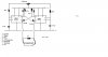
Hi, i'm trying to build a two timer astable oscillator with variable dutycycle and fixed frequency.

I built the circuit attached but i get nothing on my oscilloscope.

I didnt copy this circuit entirely i have a cicuit with 1 timer that has variable duty cycle and fixed frequency, and i have a circuit of a 2 timer astable oscillator and have tried to merge the 2 together.

I expect i have made a design mistake, could anyone help please?
 

Attachments

  • 2 timer variable duty cycle astable 555.jpg
    2 timer variable duty cycle astable 555.jpg
    43.5 KB · Views: 1,357
How is the circuit going to start? You have a long timing value on the oscillator (0.1u) and a very short timing on the trigger to pin 2. When the power it initially applied, the trigger pulses may try to work by the chips are not ready as they are still "timing-out" via the 0.1u.

The 555’s have to be turned on. Then the 0.1 will charge to 66% and pin 6 will detect the high and pin 7 will immediately discharge the 0.1, The chip will now sit in this condition, waiting for a low on pin 2.
All this has taken a long time and pin 2 has already received its short pulse and “missed it.”
That’s your problem, why the circuit doesn’t work.
 
Status
Not open for further replies.

New Articles From Microcontroller Tips

Back
Top