Hello,
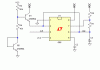
I have built an astable timer using the 555 chip. It is set up to be on for 70 seconds and then off for 2 seconds.
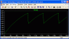
The problem is that when I first power the circuit up the on time is about 90 - 100 seconds (20 - 30 seconds longer than it's suppose to be). Once it has completed the first cycle it operates as it should with an on time of 70 seconds.
What can I do to get it to be correct when power is first applied?
Any info would be greatly appreciated.
Thanks
RC
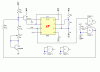
I have built an astable timer using the 555 chip. It is set up to be on for 70 seconds and then off for 2 seconds.
The problem is that when I first power the circuit up the on time is about 90 - 100 seconds (20 - 30 seconds longer than it's suppose to be). Once it has completed the first cycle it operates as it should with an on time of 70 seconds.
What can I do to get it to be correct when power is first applied?
Any info would be greatly appreciated.
Thanks
RC