Continue to Site

Welcome to our site!

Electro Tech is an online community (with over 170,000 members) who enjoy talking about and building electronic circuits, projects and gadgets. To participate you need to register. Registration is free. Click here to register now.

  • Welcome to our site! Electro Tech is an online community (with over 170,000 members) who enjoy talking about and building electronic circuits, projects and gadgets. To participate you need to register. Registration is free. Click here to register now.

555 timer: astable output

Status
Not open for further replies.

giftiger_wunsch

New Member
Hi,

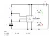
I'm new to electronics and I'm currently trying to use a 555 timer IC to make two LEDs flash on and off alternately (I later discovered that this has already been dubbed "the level crossing problem"). The circuit that I am using is attached.

However, I have run into the problem that I don't have any electrolytic capacitors, so I decided to try replacing C1 (in the circuit diagram) with a 220nF ceramic capacitor (and hoping that it wouldn't make a significant difference). I have built the circuits using a breadboard, and when I connect the battery, both LEDs light up simultaneously rather than flashing between the two.


Firstly, is this what would be expected if C1 were replaced a ceramic capacitor, or have I made a mistake while wiring the circuits?

Secondly, could someone explain why C1 needs to be a polarised capacitor, and how/why a non-polarised capacitor would behave differently?


Thanks in advance for any help :D
 

Attachments

  • 555_test_1.jpg
    555_test_1.jpg
    70 KB · Views: 1,502
Last edited:
The capacitor has nothing to do with your problem. A non-polarized capacitor will operate the same as a polarized in this circuit. The only reason a capacitor polarity is shown is when you do use a polarized cap.

But its quite apparent why both LEDs light. You have them connected in series directly across the power supply without any resistors. You are lucky you didn't blow the LEDs (I'm sure you've heard somewhere that LEDs need a resistor in series with them to limit the current (??)). The high resistance of the 9V battery is probably what saved you.

For the circuit to operate properly you need a resistor of the proper value in series with each LED to limit it's current to the desired value. Connect them in the following fashion with the 555 output connected to the junction of the top LED resistor and the bottom LED:

(V+)---LED---Resistor-|-LED---Resistor---(V-)
555 Out------------ --|
 
The 2 LED's provide the path of least resistance to ground for the 9V from the battery. Instead of current going through the 100K and 1Meg resistors and turning the 555 on, current just flows through the two LED's to ground.

The LED's should light up when power is supplied and there is no oscillation, just 2 LED's that stay on.

This circuit is not set up right for what you're trying to do.
 
Last edited:
Try this instead:

555 2 LED.JPG

If you use a second battery, then you don't interrupt the 555 circuit.

Here is what your results should look like if you put this together:

555 2 LED current.JPG

One of the square waves corresponds to the current flowing through one LED, the other square wave corresponds to the current flowing through the other LED.

Just get one more 56 ohm resistor, a 100 ohm resistor, a diode, another 9V battery, and the capacitor at pin 5 isn't necessary so you can skip that. Try it out and let me know how it works out.
 
Last edited:
He doesn't need two batteries, he just needs to connect the LED's correctly. Look here: And connect as shown in Fig. 5

Edit: depending on what values you have for the timing reisitors, you're timer might oscillate too fast to see the LED's blink. Use the formulae given in the tutorial.
 
Last edited:
The LED next to ground is on 99% of the time

Nope, just 73.3% of the time

t1/t1+t2 = R1+R2/R1+2*R2 = 68+39/68+78 = .7328...

I've tested it. You can clearly see two LED's flashing.

PS, the frequecy should be about 10Hz.

1/.693*1uf*(68K+2*39K) = 9.88Hz.
 
Last edited:
But it's quite apparent why both LEDs light. You have them connected in series directly across the power supply without any resistors.

I did consider that possibility, but the circuits I was looking at online seemed to suggest that they should be arranged like that. I must say I was scratching my head trying to figure out why I wasn't simply getting a large current through both of them and destroying them both :confused: I figured maybe the current was being divided between the other parallel circuits enough to greatly reduce that current. Obviously the 100k and 1M resistors meant that very little current was being drawn away by that circuit, but I don't know the relative impedance of the 555's positive terminal and reset terminal.


I'm going to read the other replies and try out the suggestions now.
 
Last edited:
I've modified modified my circuit now, it now looks more like the diagram attached; but now the green LED (connected to the battery's positive terminal) is always on and the red LED is always off. That seems to suggest that the output of the 555 is remaining at 0V.

Any ideas where I might be going wrong this time? :confused:
 

Attachments

  • level_crossing.jpg
    level_crossing.jpg
    75.7 KB · Views: 1,047
The circuit is correct. You have a wiring mistake or the chip is damaged or a component is not connected. If you are using a "solderless breadboard, start again and re-wire everything. Make sure the resistors are in the correct places.
1. If you have a very high impedance meter, measure the voltage on the top of the 220n.
2. Replace the 220n with 1u to 10u and replace the 1M with 47k to 220k.
3. Replace the 555.
 
I heard "start again and re-wire everything" and my heart just sank to my knees :( 
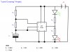
I don't have a capacitor larger than 220nF, that's why I'm using that. I calculated (correctly, I hope) that the LEDs should alternate at about 3Hz though, which should be fine. I'll try rewiring the circuits...
 
Last edited:
It's up to you, but I am just giving you ideas that will make it 100% guaranteed that you will find the fault.
It could be a faulty connection or a short between wires or even a fault in a solderless breadboard. I have no idea.
But you have to do something that will guarantee the circuit will work.
 
I've replaced the 555, rewired the circuit, and tested the resistance of the capacitor; the result is the same: the green LED is always powered on, the red is always powered off. I don't know what's meant to happen when I tested the resistance of the capacitor, but it started at about 2M and its resistance rose until it was off the scale of the meter (over 50M). I'm guessing that's a result of the multimeter charging the capacitor.

I'm not sure what's wrong with the circuit, but I have followed the circuit diagram (except for the fact that I'm using a ceramic capacitor rather than an electrolytic one) and I'm using brand new components, and have tested most of them. Are you sure there isn't still a problem with my circuit?
 
Last edited:
Are you counting the pins on the IC correctly?

Connect pins 2 and 6 together and remove the 1M 100k and 220n.
Connect pins 2 and 6 to the positive. Now connect pins 2 and 6 to the negative. Do the LEDs flash alternately?
 
Are you counting the pins on the IC correctly?

Connect pins 2 and 6 together and remove the 1M 100k and 220n.
Connect pins 2 and 6 to the positive. Now connect pins 2 and 6 to the negative. Do the LEDs flash alternately?

I'm pretty sure I've counted the pins on the IC correctly, I followed a diagram showing the pin arrangement. I tried what you suggested, and the red LED lights up when 2 and 6 are connected to negative, and the green LED lights up when they're connected to positive; I believe this is the expected result, correct?
 
This means the 555 is working.

Now connect about 100k between Pins 2&6 and pin7 Connect 47k (to 100k) between pin 7 and positive rail
 
Try what confounded said.

No capacitor at pin 5:

No cap.JPG

With a cap at pin 5:

555 2 LED current.JPG

Besides providing a straight path to ground through the LEDs, the problem with the first schematic you provided was that the LED next to the 9v battery would never have a chance to turn off unless the voltage at pin 3 was greater than or equal to the 9 volts from the battery.

With the 2 resistors though, you've now fixed that problem with a voltage divider.
 
Status
Not open for further replies.

Latest threads

New Articles From Microcontroller Tips

Back
Top