Continue to Site

Welcome to our site!

Electro Tech is an online community (with over 170,000 members) who enjoy talking about and building electronic circuits, projects and gadgets. To participate you need to register. Registration is free. Click here to register now.

  • Welcome to our site! Electro Tech is an online community (with over 170,000 members) who enjoy talking about and building electronic circuits, projects and gadgets. To participate you need to register. Registration is free. Click here to register now.

555 astable problems

Status
Not open for further replies.

bkr1969

New Member
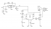
I am trying to test a simple servo controller with a 555 timer and transistor. I've read every page I can find and I still can't make it work right. I have a variable resistor between R1 and R2 and (both R1 and R2 are 4.7k) and while I can change the pot, the servo continually jitters and moves in small increments, sometimes CW and sometimes CCW. The power indicating LED (5v regulated through LM2940CT) flickers as well and the regulator really heats up. Something is obviously not right. Please help.
 

Attachments

  • circuit1.png
    circuit1.png
    14.1 KB · Views: 528
It looks like the current bypass cap you have is not big enough to provide the transient current. Do you have a bigger cap to try, or maybe put a few in parallel, and see if that help.
 
Is that C2? I've been messing with it and once it becomes clear that the 1ms pulse is the low, not the high, I changed my resistor values to R2 = 15k and R1 = 220k and it worked better. Then when I started messing with the caps, once I changed C2 to a 330uF most of the jitters went away. It doesn't seem as straight forward as every site I've read makes it out to be, but it's getting better.
 
How does that change anything? My voltage coming out of the regulator with the 22uF cap is a steady 4.89. Not doubting you, just don't understand the relationship to the timing circuit.
 
Disregard previous comment.

I think you need to have a seperate regulator for your motor. I have no experience with servos, but other motor applications it is desireable to not have the motor and control circuits using the same supply.
 
Last edited:
What is the function of the timer? Is it supposed to produce a varying duty cycle? If so, it's not a good design. Also, the wiper of R6 doesn't appear to be connected to anything.
 
How does that change anything? My voltage coming out of the regulator with the 22uF cap is a steady 4.89. Not doubting you, just don't understand the relationship to the timing circuit.

I'm speculating that your servo draws more current than the regulator could supply, and the cap is there to supply those extra current, if that's the case, a bigger cap will be needed.
 
Last edited:
Servos almost always draw more current than a small regulator can supply. Sometimes a big enough capacitor will help, but not always.

The most robust solution is to provide power to the logic (receiver, 555, or whatever) that comes from a different battery than the one which supplies the servo.
 
I'm speculating that your servo draws more current than the regulator could supply, and the cap is there to supply those extra current, if that's the case, a bigger cap will be needed.

So C5 needs to be larger even with C9 being 330uF? My understanding was that the possibility of the servo needing extra current was handled by C9. Sorry, still new to the servo control stuff. I think what I actually need to do is build a circuit using a 556 with the astable side providing the trigger signal and the other side as monostable to produce the pulses (1ms - 2ms). I will try that. Thanks for the help.
 
What is the function of the timer? Is it supposed to produce a varying duty cycle? If so, it's not a good design. Also, the wiper of R6 doesn't appear to be connected to anything.

Sorry...mis-drew that. The wiper should actually be wired to pin 7. This is just a test circuit for an animatronic series I'm reading. Eventually the servo(s) will be controlled with a microcontroller chip.
 
Status
Not open for further replies.

Latest threads

New Articles From Microcontroller Tips

Back
Top