I've come across a number of related articles but haven't seen one implemented in this fashion, I'm trying to create a real cheap boost regulator, all the other attempts I've seen use the 555 in astable mode with the timing determined by a rc pair.
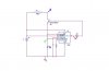
Simple 12-180V boost converter using the 555 as controller | Circuit Project Electronic
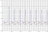
the problem with this approach is that the timing has to be set up perfectly to be efficient. Using the 555 to measure the current through the inductor would make for a far better design and allow easy current limiting for battery operations which is what I'm after. After a bit of fiddling about I created the following, when simulating in orcad it gives rather good results but building it posed problems, the circuit gets stuck in a certain state and doesn't oscillate.
Anyone up for building it to confirm that I'm not just screwing something up or have any idea why it would deviate from my simulated model? Any comments and suggestions would be appreciated.
(The transistor and inductor was chosen because that's what I had at hand)
Simple 12-180V boost converter using the 555 as controller | Circuit Project Electronic
the problem with this approach is that the timing has to be set up perfectly to be efficient. Using the 555 to measure the current through the inductor would make for a far better design and allow easy current limiting for battery operations which is what I'm after. After a bit of fiddling about I created the following, when simulating in orcad it gives rather good results but building it posed problems, the circuit gets stuck in a certain state and doesn't oscillate.
Anyone up for building it to confirm that I'm not just screwing something up or have any idea why it would deviate from my simulated model? Any comments and suggestions would be appreciated.
(The transistor and inductor was chosen because that's what I had at hand)
")
