Electro Tech is an online community (with over 170,000 members) who enjoy talking about and building electronic circuits, projects and gadgets. To participate you need to register. Registration is free. Click here to register now.
Welcome to our site! Electro Tech is an online community (with over 170,000 members) who enjoy talking about and building electronic circuits, projects and gadgets. To participate you need to register. Registration is free. Click here to register now.
Another question:
How did you calculate the value of the capacitors and the resistors in order to achieve 15min on/off square wave.
Is there any formula or equation for that?
I couldn't understand your question completely.
Is it that you want the green and red LED's to glow simultaneously, for every 4 min.
And each LED should glow for a period of 16 mins?
However whatever you requirement may be it can be acheived by simple programming.
You can take the help from any programming person.
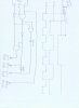
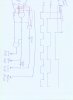
As you have asked previously about obtaining an asymmetrical square wave, you can get it with 4060. You just have to make few more connnections, which would be explained in the datasheet
hi,
Its important to remember when using external gating on the 4060, its a ripple thru counter.
You can/will get switching 'glitches' on the gate outputs, a small R/C filter on the gate outputs, is a good idea.
Hi Robert-Jan
Thanks for the schematic.
In this application, a 2min On/Off square wave doesn't exist (since there is no Q11 in the 4060), but I still need this signal.
Is there any way (a circuit or a component) that generates this kind of signal from another signal in another frequency (the 1min or the 4min On/Off, for example)?
Barakorit.
if you tune the frequency so that the 16 minute squarewave is located on pin nr 15 than your 2 min square wave will be on pin nr 6
as you did saw on the data sheet there is one output mising in the sequence so try to put your lowest frequency on the output just after the missing one so the other are in folowing order withou interuption
to lower the frequency you can increas the capacitor value and the resistor values
This site uses cookies to help personalise content, tailor your experience and to keep you logged in if you register.
By continuing to use this site, you are consenting to our use of cookies.