Electro Tech is an online community (with over 170,000 members) who enjoy talking about and building electronic circuits, projects and gadgets. To participate you need to register. Registration is free. Click here to register now.
Welcome to our site! Electro Tech is an online community (with over 170,000 members) who enjoy talking about and building electronic circuits, projects and gadgets. To participate you need to register. Registration is free. Click here to register now.
Hi guys,
Can I use a 555 component to create a generator which gives square wave of 15min "on" and 15min "off" (duty cycle=50%)?
If not, do you have another option?
Hi guys,
Can I use a 555 component to create a generator which gives square wave of 15min "on" and 15min "off" (duty cycle=50%)?
If not, do you have another idea?
Thanks a lot for the previous circuit.
One more question:
Is it possible to generate an asymmetrical square wave with this component
(15min "on" and 30-45min "off", for example)?
If not, maybe another component will do the job.
Thanks a lot for the previous circuit.
One more question:
Is it possible to generate an asymmetrical square wave with this component
(15min "on" and 30-45min "off", for example)?
If not, maybe another component will do the job.
Hi guys,
I use the 4060 to generate a 16min Off/16min On square wave.
I want the 16min On signal to turn on a green led every 4 min and keep it lighting until the end of the period (of course that there are 4 green leds).
I want the 16min On signal to turn on a red led every 4 min and keep it lighting until the end of the period (of course that there are 4 red leds).
Can it be done?
In addition, if it's possible, I want the last led in each color to start blinking when there are 2min left until the end of the time.
If not, another idea is to cause the last led in each color to blink for it's entire lighting period (approx. 4min).
I would really appreciate any assistance.
Thanks a lot,
Barakorit.
I'm sorry Robert-Jan, but I don't understand your answer.
I don't know which outputs can function the way I've just explained.
The blinking is another painful problem...
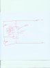
if you have a look on the data sheet of the 4060 than you see it has 10 outputs if you combine some of the outputs by the use of a AND gate than if both inputs are high the output of the AND gate will also be high
so if you have a on pulse from 16 min on 1 output than you need to find another output that is on for 8 min (pin nr 2 if you use pin nr 3 for the 16 min out)
if you put both out puts in an AND gate than the led will light up only for the time of 8 min of the 16 min
i will draw something for you but it will take some time as i am working at the moment
Another question:
How did you calculate the value of the capacitors and the resistors in order to achieve 15min on/off square wave.
Is there any formula or equation for that?
This site uses cookies to help personalise content, tailor your experience and to keep you logged in if you register.
By continuing to use this site, you are consenting to our use of cookies.