Continue to Site

Welcome to our site!

Electro Tech is an online community (with over 170,000 members) who enjoy talking about and building electronic circuits, projects and gadgets. To participate you need to register. Registration is free. Click here to register now.

  • Welcome to our site! Electro Tech is an online community (with over 170,000 members) who enjoy talking about and building electronic circuits, projects and gadgets. To participate you need to register. Registration is free. Click here to register now.

5-Way DC-DC Flyback Converter

Status
Not open for further replies.

iss407

New Member
I am designing a device that combines multiple different functions into one device. It will be primarilly a combination battery charger and regenerative motor controller, but I will add a pure sine wave inverter on if I can.

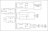
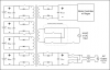
At the heart of the device will be a multi-directional DC-DC converter. I am planning to use a push-pull Flyback Converter to keep the different areas electrically isolated. I need for power to be able to flow in just about any direction to/from 5 different DC stages.

I wish to check my reasoning on how this will work:

Each DC stage will have a fixed nominal DC voltage. The ratios of the windings in the transformer will match the desired DC stage voltage. The size of the wiring and transformer core will be sized for the max desired average energy transfer.

When a DC stage is transferring energy out it will turn on the transistors and send a current pulse through the transformer. Flux will rise in the core and when the pulse turns off that flux will rapidly ramp up the voltage across the other cores until the diodes in one of the other stages become forward biased and current will flow in that coil only, charging the capacitor in that DC stage only utill the flux drops back to zero.

My theory is that whichever DC stage is transferring power out will be lowering the voltage on its capacitor only and when another pulse goes through the transformer it will be the only stage to charge. I am hoping that I do not need any other mechanisim to direct the flow of energy: One stage pulls energy out and one stage pushes energy in. The energy will flow properly controlled solely by the relative DC voltages of each stage. Am I right?

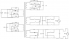
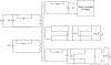
I have full bridges on everything so I can alternate pulses and not saturate the core. I also hope to be able to use the transistors as ideal diodes to increase efficiency. I am also wondering if I can add a small low power, low voltage winding around the core that is tied straight to a resister. What can I learn if I monitor the voltage on that resister? Can I measure energy transferred? Core saturation?

I plan to control each stage with its own microcontroller with one master controller taking care of all of the main switching through optical isolation.

I think ATX power supplies do something similar, using multiple secondary windings to feed different voltages. Am I correct?

Thanks in advance for your feedback.

-- Paul
 

Attachments

  • 5-Way DC-DC.png
    5-Way DC-DC.png
    8.3 KB · Views: 488
yes...and no. Flybacks are not push-pull and naturally cross regulate.

That said, there is no such thing as an ideal transformer. Flybacks charge the primary inductance and the energy is transfered to whichever winding has the lowest volts/turn on it. Saturation is determined entirely by peak primary current.

Dan
 
So reversing the pulses won't really gain anything? If so I can eliminate the H-bridge of the biggest power stages and run each with one transister. (see attached) I'd still need an H-bridge on the Rectifier as I want to be able to transfer power to the motor directly from the rectifier if I run with a generator. Also I want to feed the inverter from the rectifier for an optional power conditioner / UPS function.

Do I even need the DC stage on the rectifier? I want PFC so I'm chopping the 60 Hz AC. Can I just feed that into the transformer directly? If so I need some protection so the pulses from the transformer can't feed back into the AC line when the 60 Hz is near zero.

The single capacitor stage is for an ultra capacitor bank for the motor regen.

Thanks again for any input!

-- Paul
 

Attachments

  • 5-Way DC-DC Mark II.png
    5-Way DC-DC Mark II.png
    7.2 KB · Views: 291
you are trying to run at 60Hz? normally something like this would be a full wave bridge into a 60KHz boost PFC running the motor directly and the isolated supplies running off of that as well unless someone got real clever and did custom magnetics to tap power off the boost inductor.

Dan
 
SMPS is at high freq

Sorry for the confusion. The DC-DC switching would be at high frequency, over 10 KHz. The final freq will be determined by whatever gives the best efficiency. I may even try one of the schemes for varying the freq to reduce noise and interference.

There will be a 120VAC rectifier and a 120VAC inverter included as well as the motor controller, battery and ultra capacitor. Charging the batteries will be with household AC. The rectifier will likely be universal, 80-250VAC (or DC, for that matter). The pure sine wave inverter is added just to make the device more useful. It is going to be a controller for an electric vehicle, although I want to make it adaptable for other uses, like solar/wind storage. The inverter adds only a small cost overall. If your power is out and you have 25 Kilowatt-hour of energy sitting idle in your garage, it seems silly not to use it. If you are not using the car during the day you can even run your household A/C with it at peak demand times when prices are high and charge at night when rates are low.

I plan to design the motor controller to be universal. It will be designed as a 3 phase, variable frequency drive controller. It could also run 2 phase AC, DC, or even DC using the spare phase to control the field strength on a separately excited motor.

It could all be put together into one large controller, but if you want to hear the full insanity of my ultimate goal, read on:

Ultimately I want to have individual slave controllers that can supply about 1000 W continuous each. Each slave would have its own battery (or a short string). The AC motor and 120VAC connections would be connected in parallel, all controlled by a master controller that didn't have any power load, control only. The timing of the motor controller and inverter phases would be synced by the master controller. Power load feedback from the slaves as well as battery conditions would be analyzed by the master controller to determine how much power each slave provides. In the AC modes the slave can reduce the load simply by delaying its phases a little. Indeed, delay enough and they could draw power, but that is not planned.

I got this idea when I noticed how inexpensive per watt small 12VDC-120VAC inverters have become, a basic controller. ATX power supplies for PCs are also very inexpensive per watt, a basic charger. Combine them together and a basic 1000W slave unit can be built relatively cheaply with quantity. Centralize the expensive brains and that cost is averaged out. As a bonus, each slave can have its own isolated battery. Each battery is managed on its own so no longer is a string of batteries as weak as the weakest battery. Battery life will be extended. Batteries can be replaced individually and capacity can be added or reduced at any time. I’d get all of the best parts of a high quality battery management system and more.

Redundancy is gained; if a controller fails the system will still work at a slightly reduced capacity. Safety is improved as there won’t be a 550 Amp HV DC cable snaking through the car. There will be HV AC likes, but smaller lines that can each have individual GFCI protection.

An off-the-shelf AC generator could be towed behind an EV to extend the range. The master controller would be programmed to draw the optimum amount of power from the generator. With a universal input a home-build DC generator could be plugged in, or a 3 phase generator with a diode bridge. Frankly, just about anything that creates power could be added on. Solar perhaps.

I always wondered how much power a 60Hz HV power line radiated. Could I park under a power like and run a simple antenna for some covert energy collection? I remember visiting a HV testing facility on a college field trip and lighting a fluorescent bulb just by holding it up. Freaky!

It wasn't until later that I realized how many other uses this could have: UPS, line conditioner, frequency converter, solar/wind storage for off-grid or on-grid with power grid feedback.

Before any of those crazy ideas can see the light of day I need to get a basic working proof-of-concept prototype. Before that I need to finalize my design, and so here I am.

So, just how crazy am I?
 
I too would like to hear some ideas on this as well.

Here is how I would aprach it. If you are going to run a 3 ph motor with a variable frequency drive system you may be money ahead to mad scientist a factory made VFD unit to suite your voltage and current range. alot of the newer ones run the logic circuits of of a switcher of some type. the circuits themselves are low. around 5-12 volt on the ones I have. the switching side that runs the motor can be reworked to run higher powered switchs with a little tweaking of the current feed back loop. If its using voltage controled switches like industrial mosfet or IGBT's.
Most VFD units have dynamic breaking built in. they dump the return power to a resistor bank but i dont see why it could not just go to the battery source thats driving the EV.
Theoretical of course!
once you factor real world power consumption going into the battery charging and inverter losses just leave the house power turned on. your money ahead believe me!
unless you pay 30 cents akwh and off peak is 2 cents per kwh.

If your going to Grid Tie to feed power back that you got at off peak times and stored in the EV battery to then later reverse the full rate meter just accept that your trying to steel off peak to run peak loads! Then set up a small low voltage high current transformer to creat an isolated current loop through the off peak meter. It will spin like mad and rack up KWH's while the peak rate is bearly moving.
Around here the peak rate meter reads everything. the off peak is down line from that. your monthly bill is calculated as, Total KWH - off peak KWH = your peak rate bill. and the off peak rate is directly from the off peak meter KWH reading.
this set up could be different from location to location too.
The point is: Stealing is Stealing no mater how elaborate the plan is to make yourself feel justified by doing it! If your going to steal electricity why waste time and effort on a Rube Goldberg contraption if you dont need one.
Grid tie an alternate energy source like wind or solar and now you are money ahead and far less likely to get tossed in jail for it, pirate GTI or otherwise!
 
Around here the peak rate meter reads everything. the off peak is down line from that. your monthly bill is calculated as, Total KWH - off peak KWH = your peak rate bill. and the off peak rate is directly from the off peak meter KWH reading.
this set up could be different from location to location too.
On the other hand if you had the storage capacity it would be completely legal to store the energy off peak and feed the grid on peak.

With ideal electronics and storage you would be easilly turning up the off peak while turning down the on peak. If your formula is accurate even with a 30% storage loss and a 20% conversion loss you could have a an electric bill of zero. The problem is the cost of the storage. Now, if I had the money to burn it would be a lovely thing to do just to get a good laugh when the jerks took me to court and I got to stick them for unjust prosecution.

On a more realistic level I would build a thermal well and a monolythic dome with skylights to minimize my bills on a permanant basis. And of course developed an inexpensive electric vehicle with a 95% eff motor and nickel-zinc batteries :)

Dan
 
Last edited:
If your going to Grid Tie to feed power back that you got at off peak times and stored in the EV battery to then later reverse the full rate meter just accept that your trying to steel off peak to run peak loads! Then set up a small low voltage high current transformer to creat an isolated current loop through the off peak meter. It will spin like mad and rack up KWH's while the peak rate is bearly moving.
Around here the peak rate meter reads everything. the off peak is down line from that. your monthly bill is calculated as, Total KWH - off peak KWH = your peak rate bill. and the off peak rate is directly from the off peak meter KWH reading.
this set up could be different from location to location too.
The point is: Stealing is Stealing no mater how elaborate the plan is to make yourself feel justified by doing it! If your going to steal electricity why waste time and effort on a Rube Goldberg contraption if you dont need one.
Grid tie an alternate energy source like wind or solar and now you are money ahead and far less likely to get tossed in jail for it, pirate GTI or otherwise!

Actually, it is not stealing at all. The power companies sometimes do the same thing, even pumping water uphill at night so they can run it through a turbine at peak times. They want to lower their peak demand and having it fed in from a customer is fine with them. That is why they want customers to go to variable pricing. Feeding energy back to the grid at peak times has been listed as one of the potential benefits of electric cars.

That would be an incidental use anyway. With efficiency losses and reduced battery life factored in it would only make sense when the demand for power was huge, and at times like that the power companies will take everything they can get to meet the demand. It does make a lot of sense for a solar/wind use though.

Back to the motor control, one of the big benefits of the 3-phase AC motors in electric cars is the regen braking. It is not theoretical, it is very common in AC systems. I know that microcontrollers are being used to control 3-phase inductions motors all of the time, as well as Brushless DC motors. That aspect isn't a problem. My big concern there is matching many different slaves in timing. Then again, it is done all of the time in 120VAC UPS systems, or to feed power back to the grid. Doing it with 3-phase is basically just the same thing done three times.
 
You may be right about that. I set up a all electric heat system and electrical system for a friends shop. (400 amp service) I did the full install from the transformer in.

The reason I mentioned the stealing off peak to run peak loads is I had a good lecture on what OFF peak is intended for right from the power company guys that checked the install over before first power up.
My friend wanted to set up the whole place to run through the off peak meter and just turn that meter on/off with the off peak controler.
Great big NO! is what we got. The peak rate is what the power company makes the most money on. Plus Off peak is what its name is all about. it can be remotely shut off at peak times.

Off peak is for non critical high drain stuff that can sit without power for a few hours at a time. Just turning the off peak meter off and getting every thing at full rate does not cut it here.
The reason its called off peak is because your power company has deliberate control of when its on. They can turn off a lot of power draining high load devices to keep from overloading the supply system. The only reason you get a break on the power cost is because they can control its running times.

Pulling off peak and back feeding it to the peak rate meter is a no no here.
Yes they get to store energy for high demand times! But us customers are supposed to pay for it full rate anyway.
If you charge a big battery set with off peak and run solely off it at peak rate time yes then its legal just dont back feed to cut your peak bill or run anything off the battery while its charging.
And check out your companys list of aproved devices. An EV or battery bank charger charger may or may not qualify for off peak load usage connection. The rules for what is off peak load do vary from place to place.

Yea its strange and a bit dumb I know, but how many dumb rules are there in the world we live with every day.
Someplace else all of this may be totaly legal to do that at the customer level but I was told a very strong NO about it here. Thats where my info came from.
actually it should not matter where the energy comes from, in the US it is legal to feed the power line back through the meter. By law they have to buy back the energy we feed back into the lines, no matter how much they might not like it. Were it not so, no one would send their wind and solar back into the grid.

Essentially, all the renewables are allowed to power the grid as though it were a battery, effectively selling the peak time energy to the utility and buying it back overnight when it is not peak. Individuals are allowed to feed the grid pushing the meter backwards as long as they have approved equipment doing he feeding and power switching.

That is the law in the US, no matter what the utility companies would prefer.

Dan
 
Pulling off peak and back feeding it to the peak rate meter is a no no here.
Yes they get to store energy for high demand times! But us customers are supposed to pay for it full rate anyway.
If you charge a big battery set with off peak and run solely off it at peak rate time yes then its legal just dont back feed to cut your peak bill or run anything off the battery while its charging.
And check out your companys list of aproved devices. An EV or battery bank charger charger may or may not qualify for off peak load usage connection. The rules for what is off peak load do vary from place to place.

Yea its strange and a bit dumb I know, but how many dumb rules are there in the world we live with every day.
Someplace else all of this may be totaly legal to do that at the customer level but I was told a very strong NO about it here. Thats where my info came from.

I'm also not talking about two meters. I have one meter installed but it is electronic and logs usage by time of day. I can go online and get information about what the rates are going to be at different times of day. If I fed power back through the meter I would get money back for the current rate. I would make a lot more per KWH feeding during the day than at night. For a solar/wind application it might make sense to store that overnight energy (wind only, I guess) and feed it in the next day.

I got this meter so I can charge my car overnight when the rates are low.
 
You got me beat on this one!
But thanks for pointing my mistake out, I will openly admit I was way off on the stealing part! Sorry, My Bad!

I am aparently being mislead or misinformed by the locals. I have heard that about the grid battery concept many times but cant get a staight local answer. literaly no one is doing it yet localy that I have been told of so there is no real accurate info to work with even from the utilities guys themselves.
The utility guys talk about wanting someone to do it but wont pay for it of course! But being self funded I may actualy get be the first true local test animal!
What casual dicussions I have had with them sounds like they will give me full suport on the actual setting up and getting it done legaly. But I still have to pay for my side of the system of course!

Those that do talk about it want someone else to pay for it. The little bit of local speculation is more about how to feedback at a large enough scale to make money. And again the wanters want someone else to fund the machinery, install, and upkeep while they get the profits.

You pay for it and I will play and profit with it! Anyone ever heard of that concept before?

You have convinced me that the EV battery concept may be more feasable now.
 
well for starters, those inverters are cheap because they don't put out anything resembling a power line, only square waves.

Frankly a universal mains computer supply would be happy running on 150VDC and happier running on 350VDC.

I knew the logging meters existed but did not know they were in common residential use. It would take a prohibitive amount of batteries to make any money. you are better off with wind in a windy location.

looking at it another way your stove takes a 220V 40A breaker. if you run it at full bore for 10 hours that is 88KWHrs per day or 2600KWHrs per month. I currently pay $0.10/KWHr + about $0.10/KWHr in taxes and service fees-the sneaky jerks (since they were not allowed to tack it on to the actual cost for energy they called it something else and tacked it on anyhow). That means I would probably only make $70/mo for 180KWHrs of battery and electronics capacity, assuming it costs half as much at night and they are not paying me for the extra ten cents in fees.

On the other hand if you are running a lot of AC in the summer it could be saving you $200/mo for a few months out of the year but does that justify the $10K or more in batteries and equipment?

Dan
 
You have convinced me that the EV battery concept may be more feasable now.

Now that we agree it is feasible legally, what about electrically?

I've attached the latest design. Would IGBTs or FETs work better? I put two in each circuit so I can keep current from flowing either way if I need to. I would like to use the FETs as ideal diodes if I can.

I've read that some optocouplers can generate enough voltage to turn on a FET without any additional power. Is this so? If so I am surprised no one has built a power FET with an optically isolated gate built in.

I want to be able to transfer 1000W continuously. That would be all of the different combinations of power transfer added together. I'd like to be able to push 3 times that for 10 seconds or so, for acceleration or regen braking. If I figure 12V nominal for the battery (13-14V most of the time) that would be about 80A continuous draw from the battery. What max pulse current should I plan for the FETs on the battery?

The motor controller stage and AC stages will have much less current. If I want 240VAC out for the Inverter I need about 350V there and the motor controller should be about that voltage as well. 5 A continuous is plenty there. I'd like the universal AC/DC input to work down to about 80 V, so 15A continuous there should work.

The Ultracapacitor is an issue. Max voltage on a single Ultracap is low, 2-3V or so. I don't want to stack several together because I don't want too much capacity on any one controller, I want it spread out. I don't need a lot of capacity, just enough to dump 2 or 3 times the amount of energy a 2 ton vehicle has traveling at 60 MPH. If I need to dump more than that, say coasting down a mountain, then I would dump energy into the batteries. After all, that's where the power to climb the mountain must have come from, right?

Would it be better to tie the ultracap directly to the DC stage of the motor controller? That would be about a 100:1 boost/buck ratio. I need a very low voltage drop when charging or discharging the ultracap. Efficiency isn't as key as with other parts since we are trying to recovery energy that would be wasted anyway. If we loose 30%, we still save 70%. If I want to be able to move 3000W+, it would be over 1000A. I just looked it up and the max current for a large ultracap is about 500A, so I can't dump as much energy as I want unless I stack at least two cells. Hmmm, this will require more research...

The benefit of using ultracaps is to be able to recover more braking energy that charging batteries alone can do and to reduce max draw on batteries while accelerating. It seemed logical to add an ultracap to each slave controller. Perhaps it would be better to just stack 5 or so ultracaps together in a string and attach the 5 slave controllers to the stack in parallel. Then each controller would have 10-15V to work with and they would divide the 500A or so between them. I’m gonna look into this more…

Overall, is there any major flaw I am overlooking?

Thanks,

Paul
 

Attachments

  • 5-Way DC-DC Mark III.png
    5-Way DC-DC Mark III.png
    8.5 KB · Views: 331
Wow, Ultracaps nope. You'd need a truckfull of em.
Here's some math to help you calculate how much energy you need.
**broken link removed**

Although this is not an HHO thread here's more info on just how much power it takes to move a ton of car https://www.aardvark.co.nz/hho_scam.shtmlhttps://www.aardvark.co.nz/hho_fraud.shtml

Also remember adding batteries / anything will increase the weight of the vehicle making it require even more power.
 
Last edited:
Ultracaps for Regen only

Wow, Ultracaps nope. You'd need a truckfull of em.

I don't want to run the car on ultracaps full time. Just for the burst of energy at acceleration and to store the energy from stopping. I found these supercaps online. Fully charged each one would hold about 8,000 J, or 8 Killowatt-seconds. Put 5 together and I'd have 13.5 V, 440 F capacitor capable of storing 40 KW-S.

If I have 5 slave controllers using that capacitor bank in parallel, then each could pull about 250A, or about 3KW with a fully charge capacitor. Basically that $100 or so cap bank shared between 5 controllers would allow for the controller to pull max current for the initial acceleration. As the capacitor discharges the batteries take over for long term load. That is the basic idea for a simple regen system. It would extend battery life while simultaneously increasing range and performance.
 
Sounds almost doable. But these awfull problems have stopped most of my high efficiency consepts are as follows.
How real life expensive?
How real life difficult to actualy make?
How real life long to actualy see a true avoided cost savings?
How real life practical to opperate?
How real life run around time is going to be used in practical opperation?
How real life long to actualy see a true avoided cost savings factoring this other stuff?

Once when I felt my time in life was free I did a lot of crazy super time consuming experiments.
Now that I have alot less "free" time that "free" time I do have still seems to have a price on it.
Unfortunatly sacrificing some efficiency often is more cost effective than sacrificing time you hope to have or money you should have put elsewhere.

Just a hard reality lesson I have to cope with every day. Yea I know reality sucks the fun right out of life!

Thank you very much for the real life experience. I’ve readjusted my thinking a little and I’ve attached the latest version I’ve come up with. I’ve decided to beef up a basic slave from 1000W continuous to 3000W continuous, or 4 HP. Figure 10 HP or 7500W peak for 30 seconds. I figured there was no real world situation where someone would want a single slave, not even for a motorbike or golf cart. A 4HP controller is a more reasonable minimum size and it still allows the system to be expanded one controller at a time until desired power is reached.

I designed it to support 4 separate DC storage devices. I want to be able to use batteries or ultracaps (or hampsters on wheels! Whatever.) The 4 DC storage inputs are isolated, but they can be connected together as needed. I’ve attached a few examples as well. First, 4 isolated batteries. Next a string of 4 batteries connected in series; the coils on the transformer would be jumpered in series too. Then in normal operation only the FETs on the outside of the string would be turned on and current will flow through all of the coils with minimum voltage drop. Each battery, or string of 2 or string of 3 can be used individually as well, allowing the system to maintain each battery at optimum level and load. Another option is all 4 inputs connected in parallel on one source. That allows for 4 times the power transfer, say for an ultracapacitor bank. The last option is a compromise with a string of two batteries and an ultracap bank using two in parallel. The best of both worlds as it were.

So let me run through a basic sanity check as you have suggested:

Cost effective? If I leave out the inverter that most EVs do not have and look at just the charger, controller and battery management system I find that it would cost over $6000 for a system that can support about 30 HP continuous load. Could I produce one master controller and 8 slaves for less than $6000? Maybe $1200 for a master and $600 for a slave? Millipack PMAC controllers cost less than $500 and produce more power than I’m aiming for. That’s with all the brains in the controller where my slaves will have a central control and so less complex control. I think I can keep the costs in line with other options. My system will have much more capability of course, making it all the more attractive.

Difficult to make? For me to make by myself in my garage? Too difficult for a full blown prototype, but some parts could be proven out. For me to build in cooperation with a small electronics manufacturing firm? Not overly difficult. The only part that isn’t off of the shelf is the transformer. It would need to be specially made. Cost would be high for small production runs, but it would come down a lot if it were produced in volume. One of the reasons I want it to be usable for multiple areas with only programming changes is to reduce cost with volume.

How long to see cost savings? A very, Very long time. No way this makes sense for me to build in my garage and avoid buying off of the shelf. This only makes sense if it gets manufactured.

How Practical to operate? Very, once it is finally produced.

I think the idea is worth pursuing. At the moment I just want to refine the idea and get some feedback.

Thanks,

Paul
 

Attachments

  • 5-Way DC-DC Mark IV.png
    5-Way DC-DC Mark IV.png
    9.8 KB · Views: 265
  • 5-Way DC-DC Mark IV - Examples.png
    5-Way DC-DC Mark IV - Examples.png
    16.2 KB · Views: 243
Status
Not open for further replies.

Latest threads

New Articles From Microcontroller Tips

Back
Top