Continue to Site

Welcome to our site!

Electro Tech is an online community (with over 170,000 members) who enjoy talking about and building electronic circuits, projects and gadgets. To participate you need to register. Registration is free. Click here to register now.

  • Welcome to our site! Electro Tech is an online community (with over 170,000 members) who enjoy talking about and building electronic circuits, projects and gadgets. To participate you need to register. Registration is free. Click here to register now.

5 LED Flasher Kit Mod to 9 Help

Status
Not open for further replies.

Phinehas_Rex

New Member
Lads-

So, I've recently stumbled upon this 5 LED flasher kit that I think I can modify to fit my needs. What I am looking for is this:

I want to have a Y-formation of LEDs for a dashboard "Flux Capacitor" I'm working on for funsies. Each branch of the Y will have 3 LEDs, 9 total. The flash sequence (if you've seen Back to the Future) will be Outer, Middle, Inner, and repeat.

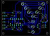
I believe, looking at this kit and its schematic, that I can modify the 5 LED flasher to 9 by wiring 3 out of the 5 into my 3-LED branches. Essentially, take 2 out of the 5, wire 3 in each of the other 3 ports, replaced the 3 Volt power source with a 9 volt, and jumper the empty spots. Make sense?

Well, that's my question. Judging by this schematic, I think...and I'm a novice...think I can do this. But, is it just as simple as: removing the 100R resistor and jumper the empty spots? What am I missing? How would you do it? Let me know. Thanks.

**broken link removed**
 

Attachments

  • Chaser Circuit.pdf
    38.9 KB · Views: 620
I would not replace the 3V battery with a 9V, you may destroy the existing IC. You can use an additional 9V battery and some transistors to switch on the additional LED's.
 
Is there anyway to find out without frying it in the process? Can the amperage be regulated so it won't affect it? I need more advice at the lowest levels! Thanks.
 
There are sooo many kits that have a 10 LED output, based on the 4017 ic...why go with a kit that is not anywhere near what you need?
Just go with 10 outputs, and forget the 10th.
You will need a small transistor on each output to drive more than 1 LED per output. The 4017 circuits also work on 6-9v as well.
If you plug your little existing 3v project into 9v....goodbye circuit.
 
Well, I purchased a 10 flasher once but there were two problems: one, the circuit board was huge and I would have to have it external to the main unit. I was looking for something that could hide in the 4x4 box. Two, I still need 3 flashing, then the next three, and then the next three in sync. So, even if I didn't use the 10th, I don't need 9 single LEDs flashing, I need it to flash 3 outer, 3 middle, and 3 inner.

Keep the thoughts coming, I still need more advice! I'm almost at my wits end with this project.
 
And what about this one marked "FK110?"

KitStop - LED Flashers Chasers
This on just may be the one. Several things about LED's you should be aware of. LED's can be hooked in series but the voltage to light them will have to be increased Most red,green and yellow LED's reguire a nominal 2V for illumination. They require a resistor in series to limit the current. Most common LED's are specified at about 20 milliamps forward current, but they are clearly visible with only 10 milliamps of forward current. If you use ohms law on the diagram you first posted(the one with a 3V battery) you will see that there is a 100 ohm resistor in series with the common lead to the LED's.
If you subtract the LED voltage(2.0) from 3V you have 1V across the resistor.
I=E/R or .01A=1V/100 ohms.
So using the FK110 and a 9V battery and 3 LED's in series with a proper resistor(about 300 ohms) the circuit should work fine.
I am inserting a table of typical LED forward voltages for you information.
 

Attachments

  • LED forward.PNG
    LED forward.PNG
    4.2 KB · Views: 339
Hi,

here is a circuit which will work with your present kit.

Supply the transistors with +9V and connect the LEDs as shown in the schematic.

Connect the LED outputs of the kit to the labelled solder pads and don't forget to connect both circuit grounds.

The THAT120 PNP transistor array can stand a collector-emitter current of 20mA. So it should be OK to work with 100Ω current limiting resistors for three LEDs in series. The resistors are calculated on the assumption that the LED forward voltage is 2.4V. For other values recalculate the values for R5 through R8.

I've also designed a single layer PCB for the schematic. Board size is 59.6X43.18mm (2.350X1.7inches) including the letter "Y" made up with 3mm dia LEDs.

Boncuk

Edit: In order to have the LEDs flash from outer to inner reverse connection pads.
 

Attachments

  • Y-SCH.gif
    Y-SCH.gif
    8.4 KB · Views: 2,282
  • Y.jpg
    Y.jpg
    50.3 KB · Views: 919
Last edited:
Thanks everyone! It may take me a minute to interpret everything. As I've said, I'm just jumping back into electronics, so I am a novice. That's what I love about this forum. There are all kinds of electronics fans out there who are so willing to help others in their "geek quest." Thanks again! I'll ask more questions if I need to.
 
Boncuk-

What would that schematic look like without the center LED in the Y formation? Just three branches of 3? Thanks so much for your hard work!
 
Boncuk-

What would that schematic look like without the center LED in the Y formation? Just three branches of 3? Thanks so much for your hard work!

Just omit R1, D0 and R5 - but it won't look like a "Y".

The transistor array constists of four independent transistors. So why not use them?

Boncuk
 
Status
Not open for further replies.

New Articles From Microcontroller Tips

Back
Top