Continue to Site

Welcome to our site!

Electro Tech is an online community (with over 170,000 members) who enjoy talking about and building electronic circuits, projects and gadgets. To participate you need to register. Registration is free. Click here to register now.

  • Welcome to our site! Electro Tech is an online community (with over 170,000 members) who enjoy talking about and building electronic circuits, projects and gadgets. To participate you need to register. Registration is free. Click here to register now.

48VDC and <= 18VDC out of 48V transformer?

Status
Not open for further replies.
It's always a good idea to add balancing resistors across capacitors when connected in series. The capacitors will have a tolerance of 20% which means that the voltage across each capacitor will be different. The problem is, it's possible that the voltage across one capacitor might exceed its maximum rating. The balancing resistors can be a high value, 1M will probably do.
 
The voltage thing does bother me somewhat, but it's really only ~5V over the rating of a single cap (counting the peak of the DC waveform), so unless something goes really wrong with one of the caps, I think they'll be safe.

I am ordering a single 3300uF 100V capacitor, so I'll just redesign the board to have solder pads to fit this one as well, so I can put the four 3300uF caps in for now, and once I get the 100V cap I can pull them out and put the new one in.

Does everything else look decently solid?

I have a rough draft of the PWM PCB layout, I'll probably finalize it tonight or tomorrow and post that for review as well.

Thanks for helping a newbie :)
 
Last edited:
It all looks to me.

Yes, I've just noticed the capacitors are rated to 50V and the supply voltage isn't much higher so even a fairly large imballance won't matter.
 
Hrmmmmm, I'm wondering if I mis-read the pinout on the LM338... looking at this:

**broken link removed**

what pins are A, B, and C?

I didn't initially see that it said "top view" on the left part, and so I assumed the view was from (what I call) the bottom; the part where you can see the insulating rings around the pins as shown in the diagram. If you look at it from the (much clearer) 3D view on the right, what do pins A, B, and C -- my markup -- correspond to? I have it wired with A as Input (2) and B as Adjust (1). C is quite unambiguous, and I have it wired as the Output (3). Do I have a different idea of what the "top" of the TO-3 is (and thus am reading it correctly) or are they essentially showing an x-ray view through the can? :p

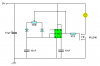
I wired it up and plugged it in for about 10-15 seconds, with ~53VDC in; it never got hot or smoked or anything, but the output pin read dead 0.0mV. Also of note, I did briefly short the output to ground as I was trying to get my leads on the connectors -- I bumped the ground alligator clip and it snapped to the next tooth, allowing it to touch the output pin. I very quickly rectified this, but, assuming I have the LM338 wired correctly, would this have permanently killed the 338?

If I did get it backwards, would the LM338 be fried from this, or would some sort of internal protection just shut it off, so that rewiring it correctly would resolve the problem? I don't want to rewire it yet in case I do have it correct, and I'd rather not have to dremel out the mounting holes in the board to accommodate reversal of the TO-3 -- especially if I do have it right currently.

P.S.: When I put the meter on the input pin, it reads the full 53V (and the 3300µF holds a ~53V charge for quite some time after I shut off power)

P.P.S.: What could I wire up to the cap so that it safely drains when power is not being applied to the circuit, without affecting current draw or the filtering capability of the cap while the circuit is powered?
 
Here's a better picture of the case.

I'm not sure if swapping the input and adjust pin will damage it, a quick glance at the LM338 schematic tells me that it might be all right.

Shorting the output to 0V when the input it >40V can fry an LM338 because the maximum input-output voltage is 40V. If you need short circuit protection then I know of a circuit which should work.

Don't worry about the capacitor being charged at 53V, for a start it's unlikely to give you more than a minor tingle and secondly it should be discharged below 20V in under 11 seconds.
 

Attachments

  • LM338 case.GIF
    LM338 case.GIF
    5.8 KB · Views: 413
it's backwards :eek:

the stupid datasheet picture is like an x-ray view, and thus indeed from the top.

what genius came up with the TO-3 package anyways? i think this would be a much better approach:
**broken link removed**
 
Last edited:
Have you got it working now?
 
Yes, I wired it up shortly after I posted (right before I had to go to work) and got it working :)

I plugged it in at work and stress-tested it (just had the fan directly connected to the output) for about 3 hours - works great!

Now I just need to make my PWM PCB (I already have a rough layout, I just need to plug it into Illustrator to make the actual layout design), solder everything, and hook it up...
 
Here's a suggestion for a simple PWM circuit, replace the bulb with the fan and connect the fan's positive to +48V.

I'd also recommend removing the 10µF capacitor or reducing it to 100nF as the regulator could be killed by the start-up transient. If the capacitor doesn't charge fast enough when the power is applied it could short the output to 0V causing the regulator to be subjected to >40V which would damage it.
 

Attachments

  • PWM 555.PNG
    PWM 555.PNG
    4.1 KB · Views: 13,734
Status
Not open for further replies.

Latest threads

Back
Top