Frosty_47
New Member
I finaly finished designing a PSU for my Audio Amp.
I apologies in advance for super large Image file...
**broken link removed**
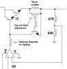
Op-amps: U1 & U2 are difference amplifiers. U1 outputs difference across the MOSFETS to U2 which than subtracts the input from the result of U1. The output of U2 is fed into the summing amplifier U3. U3 adds 9Volts to the output from U2. This keeps the gate voltage at 9Volts higher than Source. U5 outputs +55V for U1 and U2.
Transistors Q1-Q4 make-up the current limiting circuit. Rsense limits the output current: Iout = 4*Vbe/Rsense.
Q5 is NPN Darlington Pair with Hfe = 400min.
Zenner Diodes are cascaded in series to provide 65V dc input power to the op-amps.
First LM317 provides 30V reference to the U4 regulating op-amp.
Second LM317 provides 9V reference to the summing amplifier U3.
All Op-Amps are OPA-454.
T1 is a small signal transformer. 0.1 Amp output current should be enough.
Please Coment
I apologies in advance for super large Image file...
**broken link removed**
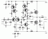
Op-amps: U1 & U2 are difference amplifiers. U1 outputs difference across the MOSFETS to U2 which than subtracts the input from the result of U1. The output of U2 is fed into the summing amplifier U3. U3 adds 9Volts to the output from U2. This keeps the gate voltage at 9Volts higher than Source. U5 outputs +55V for U1 and U2.
Transistors Q1-Q4 make-up the current limiting circuit. Rsense limits the output current: Iout = 4*Vbe/Rsense.
Q5 is NPN Darlington Pair with Hfe = 400min.
Zenner Diodes are cascaded in series to provide 65V dc input power to the op-amps.
First LM317 provides 30V reference to the U4 regulating op-amp.
Second LM317 provides 9V reference to the summing amplifier U3.
All Op-Amps are OPA-454.
T1 is a small signal transformer. 0.1 Amp output current should be enough.
Please Coment
Last edited: