Continue to Site

Welcome to our site!

Electro Tech is an online community (with over 170,000 members) who enjoy talking about and building electronic circuits, projects and gadgets. To participate you need to register. Registration is free. Click here to register now.

  • Welcome to our site! Electro Tech is an online community (with over 170,000 members) who enjoy talking about and building electronic circuits, projects and gadgets. To participate you need to register. Registration is free. Click here to register now.

433MHz RF timing - delays in modules

Status
Not open for further replies.

Yobortsa

Member
Hi all,

I'm using the following RF modules:

https://www.altronics.com.au/index.asp?area=item&id=Z6900
https://www.altronics.com.au/index.asp?area=item&id=Z6905

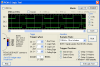
Attached below is a screen capture from PicKit2 Logic Tool.

Channel 1 shows a square wave output of about 300us from a PIC being sent to the RF Transmitter.

Channel 3 shows the received data from the RF Receiver.

There is approximately 210us delay in receiving a transition to high signal. But, there is only approximately 40us delay in receiving a transition to low signal. So the received signal is far from square wave.

The issue I have is that the delays are different. It appears one should compensate for these differences in the bit-banging routine for sending data but this isn't elegant.

Are different delays generally evident in RF modules or should I try a different brand?

Thanks,

David
 

Attachments

  • rf.png
    rf.png
    40.9 KB · Views: 483
Always different, which is why you can't reliably just send RS232 data - you need to use Manchester coding (or similar) - check my tutorials.

Thanks Nigel, some of this code is still a mystery to me but it works (now that I've swapped the RF module over for one that is serviceable).

I've modified the routine to accept a multiple length packet in the following format (all bytes except header preamble):

Code:
<Header preamble> <- 20 "1" bits followed by 1 "0" bit
Packet length (number of data bytes) <- must be 15 or less; others are masked off
Data 1
Data 2
.
.
.
Data n
Checksum (calculated by routine)

Here is the code if you're interested...

Code:
mrx_receive	; receive a full manchester-encoded packet

		clrf	len_done	; Added by DKP

s3		; set flags: first_half=1, if_short=0
		bsf 	FIRST_HALF
s4		bcf 	IF_SHORT

s5		; init before the received packet

		; set FSR to buffer start
		movlw 	mrx_buffer
		movwf 	FSR
		; set byte counter
		movlw 	(packet_len+1) ; bytes / packet
		movwf 	btcnt
		; set header receive mode
		bsf 	HEADER
		clrf 	bitcnt ; counting bit1-s in this mode

s2		; wait for a pulse
		SKH 	RXBIT
		goto 	s2

s6		; wait for end of (short) pulse up to min_2t
		clrf 	tmrval
s6_w		SKH 	RXBIT
		goto 	s7 		; goto s7 at end of pulse

		incf 	tmrval, F
		nop
		movlw 	min_2t
		subwf 	tmrval, W
		btfss 	STATUS, C
		goto 	s6_w

		; timeout, exit
		retlw 	1 		; illegal startbit

s7		; start timer
		clrf 	tmrval

s8		; if (if_short & rxbit) goto s9
		; if (!if_short & !rxbit) goto s9
		; goto s10

		btfsc 	IF_SHORT
		; if_short = 1
		goto 	s8_ss1

s8_ss0		; if_short = 0
		SKL 	RXBIT
		goto 	s10 		; rxbit = 1, goto s10

s9_ss0		; if (timer > max_2t) exit - else goto s8
		movlw 	max_2t
		subwf 	tmrval, W
		btfsc 	STATUS, C
		retlw 	2 		; signal too long

		incf 	tmrval, F
		goto 	s8_ss0

s8_ss1		; if_short = 1
		SKH 	RXBIT
		goto 	s10 ; rxbit = 0, goto s10

s9_ss1		; if (timer > max_2t) exit - else goto s8
		movlw 	max_2t
		subwf 	tmrval, W
		btfsc 	STATUS, C
		retlw 	2 		; signal too long

		incf 	tmrval, F
		goto 	s8_ss1

s10		; invert if_short
		movlw 	if_short_val
		xorwf 	flags, F

s11		; if (timer < min_t) exit
		movlw 	min_t
		subwf 	tmrval, W
		btfss 	STATUS, C
		retlw 3 		; signal too short

s12		; if (timer < min_2t) goto s14
		movlw 	min_2t
		subwf 	tmrval, W
		btfss 	STATUS, C
		goto 	s14

s13		; if (first_half = 0) goto s16 - else exit
		btfss 	FIRST_HALF
		goto 	s16
		retlw 	4 		; no mid-frame transition/out of sync

s14		; invert first_half
		movlw 	first_half_val
		xorwf 	flags, F

s15		; if (first_half = 1) goto 7
		btfsc 	FIRST_HALF
		goto 	s7

s16		; if_short is a decoded bit. Handle here
		btfss 	HEADER
		goto 	s16_not_header

		; header receiving mode
		btfss 	IF_SHORT
		goto 	s16_header_end

		; header bit is 1
		btfss 	bitcnt, 4 ; inc up to 16
		incf 	bitcnt, F  ; 16 is enough...

#ifdef NOMAXHDR
		; test for max header length
		movlw 	hdrcntmax
		subwf 	bitcnt, W
		btfss 	STATUS, C
#endif
		goto 	s7 ; loop back
		retlw 	9 		; header too long

s16_header_end	; header ends indicated by a 0
		bcf 	HEADER

		; test for min header length
		movlw 	hdrcntmin
		subwf 	bitcnt, W
		btfss 	STATUS, C
		retlw 	0x0a 		; header too short

next_byte	movlw 	0x0a
		movwf 	bitcnt
		goto 	s7 ; loop back

s16_not_header	; receiving bytes
		decf 	bitcnt, F
		bz 	s16_s4 ; if (bitcnt = 0) check for a byte-sep 1

		; if (bitcnt = 1) check for a byte-separator 0
		movlw 	1
		xorwf 	bitcnt, W
		bnz 	s16_s2

		; test for a byte separator 1
		btfsc 	IF_SHORT
		goto 	s7
		retlw 	7 		; byte-ending 1 not present

s16_s2		; bit is data

		rrf 	flags, W
		rlf 	bt, F
		goto 	s7

s16_s4		; check for a byte-separator 0
		btfsc 	IF_SHORT
		retlw 	8 		; byte-ending 0 not present


; Start added by DKP
		btfss	len_done, 0
		goto	dkp_lenbyte
save_byte
; End added by DKP


		; OK, received byte is sane, store in buffer
		movf 	bt, W			; Get byte received
		movwf 	INDF			; Save it to the buffer
		incf 	FSR, F

		decfsz 	btcnt, F
		goto 	next_byte

		retlw 	0 		; OK, buffer received

		; buffer checking is not done automatically!
		; if returned value is 0, call mrx_chk_buf to check
		;


; Start added by DKP
dkp_lenbyte
		movf	bt, W		; Get the byte value received (we know it's the length as it's the first one)
		andlw	b'00001111'	; Mask off any invalid bits so we get packet length no longer than 15
		movwf	btcnt		; Set the new byte counter
		incf	btcnt		; Add one more for header byte
		incf	btcnt		; Add one more for checksum
		bsf		len_done,0	; Set flag so we know we have length byte
		goto	save_byte	; Save the length into the buffer
; End added by DKP


mrx_chk_buf	; check buffer sanity by chksum
		movlw 	mrx_buffer
		movwf 	FSR
;		movlw 	(packet_len+1) ; number of bytes with the chksum byte
		movf 	INDF, W			; number of bytes
		movwf 	btcnt
		incf	btcnt			; add the length byte
		incf	btcnt			; add the checksum byte
		movlw 	0xff
		movwf 	bt ; used as sum register

chk0		movf 	INDF, W
		; fast CRC-8 algorithm with poly x^8+x^5+x^4+1
		; executes in 23 cycles per update
		xorwf	bt,f
		clrw
		btfsc	bt,7
		xorlw	0x7a
		btfsc	bt,6
		xorlw	0x3d
		btfsc	bt,5
		xorlw	0x86
		btfsc	bt,4
		xorlw	0x43
		btfsc	bt,3
		xorlw	0xb9
		btfsc	bt,2
		xorlw	0xc4
		btfsc	bt,1
		xorlw	0x62
		btfsc	bt,0
		xorlw	0x31
		movwf	bt

		incf 	FSR, F
		decfsz 	btcnt, F
		goto 	chk0
		; correct checksum must be zero
		movf 	bt, W
		bnz 	chk_err
		retlw 	0 		; result is in Z
chk_err		retlw 	0x0c 		; checksum error
 
There is approximately 210us delay in receiving a transition to high signal. But, there is only approximately 40us delay in receiving a transition to low signal. So the received signal is far from square wave.

The issue I have is that the delays are different. It appears one should compensate for these differences in the bit-banging routine for sending data but this isn't elegant.

Are different delays generally evident in RF modules or should I try a different brand?

Attached is the output I'm now getting with Nigel's routine (slightly modified).

Channel 1 shows the square wave output from the PIC pin to the RF Transmitter.

Channel 3 shows the data pin on the RF Receiver.

It's some pretty impressive code Nigel published considering it adjusts to missing header preamble bits and varying timing.
 

Attachments

  • rfsample.png
    rfsample.png
    12 KB · Views: 206
It's some pretty impressive code Nigel published considering it adjusts to missing header preamble bits and varying timing.

As my tutorial explains, I didn't write it :D

I just modified it to do what I wanted for the tutorial, the actual Manchester receive routines are VERY difficult to understand - but the transmit routines are nice and simple.
 
Status
Not open for further replies.

Latest threads

New Articles From Microcontroller Tips

Back
Top