Continue to Site

Welcome to our site!

Electro Tech is an online community (with over 170,000 members) who enjoy talking about and building electronic circuits, projects and gadgets. To participate you need to register. Registration is free. Click here to register now.

  • Welcome to our site! Electro Tech is an online community (with over 170,000 members) who enjoy talking about and building electronic circuits, projects and gadgets. To participate you need to register. Registration is free. Click here to register now.

433Mhz RF Module PCB

Status
Not open for further replies.
The answer depends on where the module is mounted on your board, how you will connect the ANT terminal of the module to your board, and where you plan to locate the wire antenna connection point on your board. Can you provide a drawing?
 
Hi, I the attached PCB layouts of both RX and TX which the ebay 433Mhz modules going to hook up.

The ebay 433Mhz modules have header pins & I directly insert the modules to my PCB & going to solder.Even the antenna has a header pin.The antenna I'm going to place on my PCB showed label "Antenna PAD".
 

Attachments

  • rx check.PNG
    rx check.PNG
    173.7 KB · Views: 277
  • tx check.PNG
    tx check.PNG
    118.3 KB · Views: 234
Antennas always have two wires going to them. A single wire going only to a 1/4 wavelength whip is not an antenna.
 
Hi

I'm going to use a piece of CAT5 wire or this helical antenna.It has only single end to solder.173mm length.
**broken link removed**
 
Last edited:
Hi, I the attached PCB layouts of both RX and TX which the ebay 433Mhz modules going to hook up.

The ebay 433Mhz modules have header pins & I directly insert the modules to my PCB & going to solder.Even the antenna has a header pin.The antenna I'm going to place on my PCB showed label "Antenna PAD".

OK. I recommend that you include a ground plane as shown in the attached figure. The ground plane is the area that has a grey tone to it. It is under everything except the antenna trace. This assumes your antenna sticks straight up from the pcb (perpendicular to the surface of the pcb.
 

Attachments

  • misc.jpg
    misc.jpg
    156.4 KB · Views: 176
OK. I recommend that you include a ground plane as shown in the attached figure. The ground plane is the area that has a grey tone to it. It is under everything except the antenna trace. This assumes your antenna sticks straight up from the pcb (perpendicular to the surface of the pcb.

Thank you very much.That is transmitter PCB & I'll add a groundplane as you suggest.What about reciever side do I need a groundplane to that as well...!!
 
Thank you very much.That is transmitter PCB & I'll add a groundplane as you suggest.What about reciever side do I need a groundplane to that as well...!!

Yes, the RX board will need a ground plane also. It should be designed using the same principle as the tx board. By that, I mean that the ground plane should cover all the board except under and close to the ANT trace.
 
Antennas always have two wires going to them. A single wire going only to a 1/4 wavelength whip is not an antenna.

Mike, you’ve got the right idea, but here are some interesting details that you might not be aware of. The point where RF power is fed into an antenna system is called the feedpoint. The amount of power that a transmitter can push past that point depends entirely on the impedance of the transmitter output (the source impedance) and the impedance looking into the antenna feedpoint. Remember your Thevinin equivalent circuit. If the generator (the transmitter circuit board) were infinitesimally small, and the antenna were any length of wire, the input impedance would be near infinity and no power would transfer from the transmitter to the antenna. This is the point you are making. However, as soon as we provide any conductor of sufficient size on the transmitter side of the feedpoint, the antenna will couple to that as its “counterpoise” automatically and the feedpoint impedance of the antenna will automatically come down from infinity to some lower value. So the transmitter board automatically becomes part of the antenna system, whether we like it or not.

Now, if the transmitter board has a ground plane that is large, the antenna system feedpoint impedance comes down to a very useful and practical number. For example, with a very large ground plane that is perpendicular to the antenna wire, and when the wire is nearly ¼ wavelength long, we get a practical impedance somewhere near 50 ohms. Transmitter boards are usually not very big, so we usually have a compromised ground plane, but even in these cases, the feedpoint impedance drops to a useful value, often below 120 ohms. In a case like that, the antenna will work pretty good, just not optimally. And yet, it seems to have only one wire. The other wire is actually the ground plane of the pcb.

Now, here’s another interesting example. You remember early cellphones that had the pull-out whip antennas? These antennas were often simply ¼ wave whip antennas. These seem to have only one wire so how do they work? The other wire is the rest of the phone. The main circuit board acts as the ground plane for the whip antenna, that’s how it works.

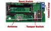
So, whenever you see a transmitter board that has one wire connection called ANT, you can assume that the “second wire” is the board itself. And we hope the board is large enough to do its job as part of the antenna and when it isn’t, well, we just live with it.

One other point worth mentioning is about your statement “a single wire going only to a ¼ wave whip is not an antenna”. Indeed, the wire going to the whip becomes part of the whip. In the case of this board, the traces and pins that carry ANT signal from the module, through his board, to his whip are also part of the antenna and their length should be calculated into the total length.
 
The transmitter is more critical, however those modules have an inductance in series with the tx ant connection, so the actual length will be less than 1/4 wave, that said a 2 wire dipole will be more effective on the transmit end, if the pcb is powered by say a wall wart its cable will act as a ground plane.
The Rx end is less sensitive to length as the i/p impedance is high.
 
Last edited:
Hey Ron, I have been an active Ham for ~50years. I know all about Off-center-fed dipoles and feeding vertical mobile antennas. I own **broken link removed**

I am using several of the 315MHz transmitters/receivers for a project here. I made some range measurements comparing monopoles with just the pcb as a counterpoise on the ebay 315/433 MHz modules to full-length dipoles mounted externally. The full-size dipoles won by a huge margin...

Look at the pictures attached to post#14 in this forum thread.
 
I am using several of the 315MHz transmitters/receivers for a project here. I made some range measurements comparing monopoles with just the pcb as a counterpoise on the ebay 315/433 MHz modules to full-length dipoles mounted externally. The full-size dipoles won by a huge margin...

A correctly sized 1/4 wave whip, on a suitable ground plane, is identical to a dipole - the ground plane effectively is a 'mirror' which created the other half of the dipole - obviously a 'bit of wire' stuck on the module is a very poor imitation.

Your huge margin (and it would be HUGE) is down to the aerial been external, and correctly sized :D

Incidentally, for the external aerial, did you mount the RF module close to the aerial, so the RF path was nice and short, and have longer wires feeding the module.
 
The RX is mounted inside the PVC tube, so the "feedline" is about 4cm long. I optimized the distance of the dipole away from the vertical metal wall so as to shape the pattern in the direction I wanted maximum reception range.

The choice of horizontal polarization is because I transmit from inside a car, and I determined empirically that the primary field radiated through the windshield is horizontal, regardless of how the keyfob is held...
 
Hey Ron, I have been an active Ham for ~50years. I know all about Off-center-fed dipoles and feeding vertical mobile antennas. I own **broken link removed**

I am using several of the 315MHz transmitters/receivers for a project here. I made some range measurements comparing monopoles with just the pcb as a counterpoise on the ebay 315/433 MHz modules to full-length dipoles mounted externally. The full-size dipoles won by a huge margin...

Look at the pictures attached to post#14 in this forum thread.
Mike, I am really impressed with these small antenna analyzers. Back when I was a youngster in my first engineering job we had to make do with measuring impedance with a very finicky vector voltmeter that was a pain to hook up. Naturally, I was smitten by the first automatic vector network analyzer that I got to use, which was an HP, something prior to the 8753 series I think. So, of course when the opportunity to get my own personal vector network analyzer came up I grabbed it. That was back around 2000. Nowadays, many hams can afford to buy an instrument like the one you have, that measures impedance and I think that is just great. Someday maybe I'll get one too, since my 8753E is not very portable!

You and I might have different definitions of "huge" when we talk about compromises in antenna gain. As a ham, I am something of a purist about optimizing gain and would consider a -5 dBd gain as being bad. Perhaps you would too. But as a designer of portable wireless products I have been forced to focus on electrically short antennas and highly compromised and lossy ground planes, and to accept gain and patterns that would disgust most hams. I endorse your coaching that we should strive towards a half wave dipole or good quarter wave monopole when circumstances allow.
 
Hi. From all of your suggessions I learned a groundplane is really for what purpose...:)

My target is to build a reliable wireless transmitter & reciever which can work about 60-70meters.please note that the transmitter must be place inside a professional looking small enclosure.so the antenna must design to fit it.

I want something like honeywell 5816 transmitter where the antenna is placed inside the enclosure horizontally and it is working 200feet from a 3V battery.

Actually my modules are 315mhz.can i build a link like honeywell design from these ebay modules?
 
Last edited:
If you plan to put the transmitter board inside a box, then we should ask the question...what is the box made of? If it is metal, then the portion of the antenna that projects above the surface of the box will couple with the box and the box will automatically become a counterpoise for antenna current. In this case, it would be wise to use a transmission line rather than a single conductor to feed power to the base of the antenna. If the box is plastic, then it will not introduce any new problems.
 
Hi my box is plastic.don't know the sizes yet.after making a compact transmitter unit i'm going to find a enclosure.
 
I mean something like this.its honeywell 5816.it uses a horizontal antenna.so i can use a flat enclosure.
 

Attachments

  • DSC_2166w-1.jpg
    DSC_2166w-1.jpg
    28.5 KB · Views: 184
Status
Not open for further replies.

Latest threads

New Articles From Microcontroller Tips

Back
Top