Continue to Site

Welcome to our site!

Electro Tech is an online community (with over 170,000 members) who enjoy talking about and building electronic circuits, projects and gadgets. To participate you need to register. Registration is free. Click here to register now.

  • Welcome to our site! Electro Tech is an online community (with over 170,000 members) who enjoy talking about and building electronic circuits, projects and gadgets. To participate you need to register. Registration is free. Click here to register now.

42-58Vdc (0.3mA) -> 5Vdc (0.02mA)

Status
Not open for further replies.

Romadon

New Member
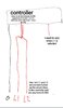
I have a 3 pole switch I want to use to restrict and derestrict an Ebike. The controller only has 1 input for on/off which means both positive poles of my switch need to be connected to it

Problem, I need to feed a 5v signal ONLY when 1 of the 2 poles are selected.

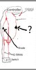
When the 5v signal is received the bike is restricted, my switch looks like this "L1/0/L2".

I presume I want to put a diode on L1 just before it joins to L2 and feeds the controller and take a spur off of L1 before the diode, now when L2 is selected on the switch the spur from L1 will not be live, correct?

The spur coming from L1 will then feed the signal wire (thus restricting the ebike) on the controller, and only be live when L1 (low power mode) is selected on the switch, correct?

L1 and L2 have variable voltage of 42-58Vdc and draw 0.3mA, I want the spur from L1 to have a fixed voltage of 5Vdc, its draw is 0.02mA. What is the correct way to do this? A very rudimentary diagram would be helpful, I have no clue about electronics.

I did look at a DC/DC buck converter but, most only allow from 40Vdc to 5Vdc and even the higher voltage variable ones mostly say Max -33v output, which ofcoarse is no good to me

1. Will my idea work, with a spur before a diode on L1?

2. Should I use 2 variable buck converters in parrallel on the spur, 42-60Vdc -> 30Vdc -> 30Vdc -> 5Vdc?

3.. Is there an easier cheaper way?
 

Attachments

  • Screenshot_20210516-015124_Chrome.jpg
    Screenshot_20210516-015124_Chrome.jpg
    81.6 KB · Views: 155
Are you using the switch to directly disconnect / connect the main battery power, or is it just a control signal being switched (a thinner wire)?

I'm guessing the switch has a centre off position, otherwise it has no reason to be connected inline with any other circuit.

Using a diode in the main battery connection will need a rather high rated diode, with a heatsink. And a rather high rated switch!

The 5V signal at 0.02mA is trivial - just a 100K resistor and 4.7V zener diode, plus another 100K from the high voltage side to ground, to discharge any leakage. The resistors would be dissipating a small fraction of a watt.

No the actual switch just connects to the controller, so I should put a 100v diode on L1 to stop the spur off L1 going live when L2 is selected (L1 and L2 are joined together close to the controller, because my controller only has 1 wire for on/off which L1 and L2 need to go to). Anywway.

1. 100v diode on L1 inbetween the spur and where L1 joins to L2.

2. 100k ohm resistor on the spur ( the signal wire draws 0.02mA at 5v which is 250k ohms resistence, this essentially will drop the 42-58vdc to around 12-18vdc to feed the zener right?

3. 4.7v Zener diode inbetween 5v signal input and 100k resistor.

Am I understanding this correct?
 
OK, so it's a low current switch; that's fine.
So the arrangement is:

Power to the common of the switch.
Diode anode to L1 and cathode (banded) to L2.

You can use something like a 1N4004 or anything up to 1N4007 diode, a higher voltage one is fine and may be easier to get.

The existing on/off wire connects to L2, and will be powered in either switch position.

A 100K resistor from L1 to ground (controller common or battery negative).

A second 100K resistor from L1 to the cathode (banded) of the 4.7V zener. Anode of the zener to ground.

The resistors could be rather lower, anything down to 10K as long as you use half watt resistors. You can use 22K, 47K or whatever you can get easily. Even at 10K, the zener current is only around 5mA or so, meaning roughly 25mW dissipation in the zener.

You can think of a zener as something like the electronic equivalent of a "pressure relief valve" - it will take whatever current is needed to prevent the voltage across it rising significantly above it's voltage rating, up to the point it overloads.
 
rjenkinsgb thats gone completely over my head, can I just add a loop on to L1, place 2 100k resistors on the loop and take a feed from said loop inbetween resistors, to drop voltage from 42-60v > to 21-30v and then use a 5v-40v> 5v buck step down of coarse put a rectifying diode on L1 above loop and before it connects to L2, I have attached an image below.

Like this when L1 is selected L1 and L2 will be live, and the power inbetween the 100k resistors will be 21-30v correct?

But when L2 is selected the loop on L1 will not be live because of the rectifying diode correct?

L1 will send power to the 5v signal and restrict the bike but L2 will not, correct?
 

Attachments

  • Screenshot_20210516-144242_Gallery.jpg
    Screenshot_20210516-144242_Gallery.jpg
    364 KB · Views: 161
The voltage at the junction of a resistor divider is only valid with no load connected.
Any load that draws current has resistance, and you have to calculate the divider WITH that extra resistance as part of the formula; and with such as a buck regulator, the "resistance" depends on many things.

This is a quick rough of the circuit I was describing:

limiter_switch.png


V1 is the battery, L1 - L2 is supposed to be the the switch (names from your original post).

The rectifier diode connects between L1 and L2, with the on/off control wire taken from L2. (R1 represents the control unit input for that).

R2, R3 and D2 are the other added components. R2 is acting as a bleed resistor to discharge any stray voltage when the switch is in the L2 position.

R3 limits the current to the zener and the zener sets the "5V" level when the switch is in the L1 position.

R4 represents the "limit on" input in the control unit. (using those is a lot quicker and easier than creating a "Control unit" special component - just ignore them! )
 
Status
Not open for further replies.

Latest threads

New Articles From Microcontroller Tips

Back
Top