Continue to Site

Welcome to our site!

Electro Tech is an online community (with over 170,000 members) who enjoy talking about and building electronic circuits, projects and gadgets. To participate you need to register. Registration is free. Click here to register now.

  • Welcome to our site! Electro Tech is an online community (with over 170,000 members) who enjoy talking about and building electronic circuits, projects and gadgets. To participate you need to register. Registration is free. Click here to register now.

4 bit up/down counter

Status
Not open for further replies.

BruceBruce

New Member
Hello Everyone,
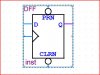
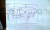
I'm trying to design and test a 4-bit version of an Up/Down Counter using D Flip flops. I need it to be Up'/Down = 0 then the circuit should behave as an up counter. If Up'/Down = 1 then the circuit should behave as a down counter. I also need to create an input waveform file to test the procedure in a "full count" up and down.

Oh i need to design this in Quartus II software. It can be a schematic or VHDL code.

Thanks for the help hopefully.
 
Do you mean equal to or greater than and equal to or less than.

<= test for less than or equal, result is Boolean
>= test for greater than or equal, result is Boolean

Rather than just =?

Ron
 
Well a 4 bit counter is 2^4 or 0 to 15 in count. Actually a count up of 0 to 15 or count down 15 to 0. So when we make the statement:

I need it to be Up'/Down = 0 then the circuit should behave as an up counter. If Up'/Down = 1 then the circuit should behave as a down counter.

So if the count = 1 You want to count down to 0 but what if the count is greater than one like 2, 3, 4 or greater? Thus for example we have equal to or greater than which I thing is what you want, that would be:

If my.count >=1 then
count.down

The result would be a Boolean as in a 1 or 0. More operator examples:

= test for equality, result is boolean
/= test for inequality, result is boolean
< test for less than, result is boolean
<= test for less than or equal, result is boolean
> test for greater than, result is boolean
>= test for greater than or equal, result is boolean

If I have time later today at work I'll try to give you a few examples.

<EDIT> Actually a good example of a SYNCHRONOUS 4-BIT UP/DOWN COUNTER is a counter like the 74193 series. This is the data sheet and the data sheet provides full logic drawings breaking the chip down. Try to follow the logic and read the description of what the chip does. That should help you out. </EDIT>

Ron
 
Last edited:
I could draw the whole digital schematic, but that would get kinda big i think.
I dodnt know how much you know about digital tech, but i could try to help you on your way.
 
Do you mean equal to or greater than and equal to or less than.

<= test for less than or equal, result is Boolean
>= test for greater than or equal, result is Boolean

Rather than just =?

You may be overthinking this.

I think the O.P. means they want a signal that they call "Up/Down" to control whether it's an up-counter or a down-counter. So that signal would either be high or low to control the behavior of the circuit.

I could be wrong, though. O.P.: is this what you meant?
 
yah thats exactly what i mean carbonzit and feel free to draw it Robin91 lol.

would it look similar to this but with d flip flops in it and the OR gate only going to the D input instead of the J and K inputs.

Ill post up my drawing of what i think it is tonight. I gotta submit this by midnight on friday though.
 

Attachments

  • Capture.JPG
    Capture.JPG
    30.2 KB · Views: 1,336
You may be overthinking this.

I think the O.P. means they want a signal that they call "Up/Down" to control whether it's an up-counter or a down-counter. So that signal would either be high or low to control the behavior of the circuit.

I could be wrong, though. O.P.: is this what you meant?

Yep, over thinking and reading into. :)

Ron
 
ok so using that design for a 4 bit up/down counter using j/k flip flops i got this so far. I dont know what to put as an input for the first D flip flop. In the diagram it has something that says Vdd(not sure what that is) that goes into the first flip flop. How do i make that so it goes into the D flip flop. Also when i design this in quartus do i just make "up/down" a regular input?

Ill owe somebody big time if they help me get past this lab lol.

heres what i got so far:
**broken link removed**

Uploaded with ImageShack.us
 
hmm where did my post before the picture one go. oh well. well i dont know what to plug into the d input of the first FLip flop. In the diagram for the JK flip flop 4 bit counter it had Vdd as the first input to j and k. What is Vdd and how do i incorporate that into my diagram. Also the "up/down" is that just a regular input labeled up/down? i know the q0-q3 are all the outputs but where do i end that last "NOT Q" to?

Hopefully you guys can answer this and help me fix the drawing. Ill owe whoever helps me out big time. If you would like to email me than please send it to chaostoyota@gmail.com. Thank you.

Or ill try to make it worth your time somehow.
 
Last edited:
heres the new design. let me know what you think. I gotta turn this in by midnight tonight(california time PST)

Also in the quartus program how do i get "Q NOT"? there isnt a pin for it on the D Flip Flop icon. do i just run a Not gate off the Q? i attached a pic of it
 

Attachments

  • Capture2.JPG
    Capture2.JPG
    38 KB · Views: 979
  • IMAG0126-1.jpg
    IMAG0126-1.jpg
    1.5 MB · Views: 2,529
Status
Not open for further replies.

Latest threads

New Articles From Microcontroller Tips

Back
Top