Continue to Site

Welcome to our site!

Electro Tech is an online community (with over 170,000 members) who enjoy talking about and building electronic circuits, projects and gadgets. To participate you need to register. Registration is free. Click here to register now.

  • Welcome to our site! Electro Tech is an online community (with over 170,000 members) who enjoy talking about and building electronic circuits, projects and gadgets. To participate you need to register. Registration is free. Click here to register now.

4-20mA Circuit

Status
Not open for further replies.

Mark_R

Member
Hi,

Setting up an input for a 4-20mA Circuit to a 5V ADC, Looking at the standard 250 ohm resistor to create the 5V signal at 20mA but I'm concerned with blowing the ADC if someone crosses the field wiring and sticks the excitation voltage (likely 24V) to the input.
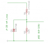
I was fiddling with a zener / fuse setup (see attached) but the ADC lists 5.3v absolute max, and I can't come up with a combination of values that would work across the tolerance window. I ether get into the zener range too early or over voltage the input of the ADC.

How is this normally dealt with? (full isolation would be awesome!)
 

Attachments

  • 4-20.JPG
    4-20.JPG
    74.3 KB · Views: 3,234
Last edited:
Hi Mark.

I would like to ask you for a little background on your project.

I work in an industrial setting and am familiar with control instrumentation (I'm an I and A technician)...However I predominantly work with lab analyzers. It's been years since I calibrated a transmitter so I'm rusty. But the key question I have, is this project for an industrial or biomedical application, or is it a personal project you're doing at home?

Reason being, I know my company has strict policies and guidelines about modifying equipment or processes...i.e "don't". Not so much a problem when your trying to control the temperature of bathwater, much bigger deal if your supplying 200 lbs of steam to a boiler or reactor.

So maybe some background?
 
i.e. the brand and function of the transmitter and sensing element (honeywell, foxboro, rosemount? thermocouple, dP cell?) the process being sensed, (fluid, level, flow, catalyst, furnace, tank, vacuum?) and the control element. PID. PI. or just P?

I'm asking as much out of curiosity as anything, but I'd feel better if you said your working on a system for baking gingerbread for Christmas :)

A quick Google search led me to this technical bulletin:

https://www.electro-tech-online.com/custompdfs/2009/11/AN3195.pdf

Looks like it discusses fault protection for a 24V source and A/D converting the 4-20 by sensing across a 2 ohm resistor , making it 8-40 mV, and the amplifying it and converting it to a .8 to 4.0 volt signal.

Maybe this kind of circuit is what you're after?
 
Last edited:
Mark R, why not simply use a clamp diode to VCC, and GND for that matter?
 
Sceadwian, in this application I do not think he is trying to protect the load from the source, but rather the source from the load.
 
Either way clamp diodes will work. He said he wanted to protect the ADC which is what is reading the voltage dropped by the resistor, I read that as trying to protect the load, as the source of the current is an external device.

I'm not quiet sure what you're protecting against though, you need to protect from reverse voltage of the sense resistor that's about it. If you can apply 24V directly to the ADC then that means your have an exposed circuit board or a bad connection layout. You can't protect a circuit from stupid people if it's all available like that.
 
You are correct that the ADC is what he is trying to protect. I misread. Usually fault sensing in 4-20 mA loops is for shorts.

And that is what usually happens. This is not a circuit board, in most cases it is hundreds of feet of cable in conduit, transmitting signals from a local transducer to a remote PLC or controller, and from that PLC to a control valve actuator. Sometimes short circuits occur, thus the limiting resistor.

I'm thinking that voltage clamping could cause problems in these kinds of circuits due to their nature.
 
How would it cause a problem? It won't even show up in the circuit until the voltage is a diode drop above or bellow the local VCC/GND connections.
 
i.e. the brand and function of the transmitter and sensing element (honeywell, foxboro, rosemount? thermocouple, dP cell?) the process being sensed, (fluid, level, flow, catalyst, furnace, tank, vacuum?) and the control element. PID. PI. or just P?

I'm asking as much out of curiosity as anything, but I'd feel better if you said your working on a system for baking gingerbread for Christmas :)

A quick Google search led me to this technical bulletin:

https://www.electro-tech-online.com/custompdfs/2009/11/AN3195-1.pdf

Looks like it discusses fault protection for a 24V source and A/D converting the 4-20 by sensing across a 2 ohm resistor , making it 8-40 mV, and the amplifying it and converting it to a .8 to 4.0 volt signal.

Maybe this kind of circuit is what you're after?

I'm trying to setup a PID loop to maintain feedwater level for a 15.5Mbtu steam boiler :p

Kidding. This is not for control, this is for a remote monitoring system for industrial / waste water processes. kind of like SCADA without the "C".
I looked at the Maxim doc before, but it seems to be a solution for limiting the excitation voltage (source). This system will be installed by a third party, they will provide the power supply and / or transmitter

Either way clamp diodes will work. He said he wanted to protect the ADC which is what is reading the voltage dropped by the resistor, I read that as trying to protect the load, as the source of the current is an external device.

I'm not quiet sure what you're protecting against though, you need to protect from reverse voltage of the sense resistor that's about it. If you can apply 24V directly to the ADC then that means your have an exposed circuit board or a bad connection layout. You can't protect a circuit from stupid people if it's all available like that.

If we are talking about a powered transmitter, then that would be current limiting, no big danger, but a lot of 4-20 systems have a separate power supply with a passive transducer ==> https://www.electro-tech-online.com/custompdfs/2009/11/M3939.pdf If the run to the sensor shorts, the full voltage of the power supply would be present at the positive side of the sense resistor, no?
This is also the connection point of the adc pin, which can only take 5.3 volts before I breach the factory smoke containment system.

I re-did the math and I must have made an error before. With the resistor at the high end of the 1% tolerance, the transducer would have to exceed 5% over spec for the ADC pin to climb over 5.3V. I was getting 5.6-ish before. :rolleyes:
 
OK, here is how it could cause a problem:

A 4-20 mA signal is an analog representation of a transducer. The transmitter is calibrated (zero and span) to represent the high and low range of operation for the particular process. For example, a CONTROLLED process that ranges from 1 psi to 100 psi would be 4 mA=1 psi 8mA=25 psi 12 mA=50 psi 16 mA=75 psi 20 mA=100 psi

There would be a setpoint somewhere in the middle of that range where the process is operating normally, perhaps 50 psi.

If a disruptive condition causes a pressure increase, say of 25 psi, the transducer would sense it and adjust its output to 16 mA. At the PLC, the algorithm of the microprocessor senses a deviation from its set point. It calculates an appropriate response and sends another signal via a seperate 4-20 loop (which is also calibrated) whose responsibility is to adjust a CONTROL VALVE. In this case, the control valve would want to open wider to relieve the pressure in the system. So, the steady control condition of 12 mA loop current would hold the valve actuator at 50% travel. The upset requires it to open, for simplicities sake lets say 25% to relieve the 25% increase in pressure. So, the valve opens to 75% travel, relieving the pressure and then eventually the whole system gets back to equillibrium.

OK, I explained the system to show you how clamping it could cause trouble. If, anywhere along the circuit, the transucer is bypassed or shunted, the entire loop could be thrown out of whack and the valve actuator could slam shut or be thrown full open, creating an overpressure condition or a dump. In a system with $100,000 or more of product or raw materials, or explosive, etc etc, this could be a big deal.

Also, these PLCs often have multiple loops operating off of a single supply. If one loop gets clamped and it effects the power supply voltage for all the loops, an entire process could be sent into chaos.

Generally speaking, these PLCs have many safeguards and back-ups systems, but the point is valid.

I'm just saying, and I'm not a Process or Electrical engineer, but I'm not sure its a good idea.
 
Ah, not a control loop, just measuring. BIGGGGG difference.

Just thought of a metaphor for the clamped condition response. The result at the control valve might be like a transistor going into saturation.
 
Last edited:
No guts, no glory :)

OK, here is how it could cause a problem:

A 4-20 mA signal is an analog representation of a transducer. The transmitter is calibrated (zero and span) to represent the high and low range of operation for the particular process. For example, a CONTROLLED process that ranges from 1 psi to 100 psi would be 4 mA=1 psi 8mA=25 psi 12 mA=50 psi 16 mA=75 psi 20 mA=100 psi

There would be a setpoint somewhere in the middle of that range where the process is operating normally, perhaps 50 psi.

If a disruptive condition causes a pressure increase, say of 25 psi, the transducer would sense it and adjust its output to 16 mA. At the PLC, the algorithm of the microprocessor senses a deviation from its set point. It calculates an appropriate response and sends another signal via a seperate 4-20 loop (which is also calibrated) whose responsibility is to adjust a CONTROL VALVE. In this case, the control valve would want to open wider to relieve the pressure in the system. So, the steady control condition of 12 mA loop current would hold the valve actuator at 50% travel. The upset requires it to open, for simplicities sake lets say 25% to relieve the 25% increase in pressure. So, the valve opens to 75% travel, relieving the pressure and then eventually the whole system gets back to equillibrium.

OK, I explained the system to show you how clamping it could cause trouble. If, anywhere along the circuit, the transucer is bypassed or shunted, the entire loop could be thrown out of whack and the valve actuator could slam shut or be thrown full open, creating an overpressure condition or a dump. In a system with $100,000 or more of product or raw materials, or explosive, etc etc, this could be a big deal.

Also, these PLCs often have multiple loops operating off of a single supply. If one loop gets clamped and it effects the power supply voltage for all the loops, an entire process could be sent into chaos.

Generally speaking, these PLCs have many safeguards and back-ups systems, but the point is valid.

I'm just saying, and I'm not a Process or Electrical engineer, but I'm not sure its a good idea.

I get all that five by five. We do process controls with PLCs etc. and are familiar with the concepts and pitfalls (just this summer I cracked an expensive mold because I plugged the "A" molds thermocouple into the controller for the "B" mold. The A controller kept trying to drive the mold temperature up but was not seeing the correct feedback, by the time I noticed, the mold had overshot 40C. Stuff happens :( )
This is not the situation here. This is a monitor system for reporting tank levels, freeze protection, power fail, Etc. at remote unattended locations. No control, not tapping into loops used for the process, just calling the cavalry.
 
I figured you had to know how control loops work since you were working with a transmitter here :)

I posted the quick and dirty tutorial on the subject for the sake of future Googlers or current readers who may not know what a 4-20 loop is predominately used for.
 
You could also use an OpAmp as the current to voltage converter and add two back to back diodes on the virtual ground input. The advantage of this technique is that there would be no voltage drop (very little: mVs) on the current sense input.
The ADC may already have clamp diodes to GND and VDD. If so, add a resistor in series with the ADC pin to limit the current for extra safety:
 

Attachments

  • 4-20.JPG
    4-20.JPG
    73.2 KB · Views: 846
Here's something that's possibly a bit more practical. The ADC probably can be set for 0-2.5V range just by changing its reference. Or, maybe you don't need all the range. D1 is 3.3V which shouldn't affect accuracy, yet limits the ADC input to well below 5V.
 

Attachments

  • PLC Clamp.png
    PLC Clamp.png
    8.5 KB · Views: 792
Other Options

Some interesting ideas here:

PLC DEMO SYSTEM | Evaluation Boards/Tools | ADR02 | Voltage References | References | Analog Devices

(semi) Detailed discussion of the included circuits, particularly the circuit protection, here:

Process Control: Analog Dialogue: Analog Devices

The input circuits shown offer high ESD protection and noise rejection as well ass FULL ISOLATION. The downside is that the components are a bit pricey.

Edit: the full schematic is available for the asking via e-mail. I asked.
 
Last edited:
Status
Not open for further replies.

Latest threads

New Articles From Microcontroller Tips

Back
Top