Continue to Site

Welcome to our site!

Electro Tech is an online community (with over 170,000 members) who enjoy talking about and building electronic circuits, projects and gadgets. To participate you need to register. Registration is free. Click here to register now.

  • Welcome to our site! Electro Tech is an online community (with over 170,000 members) who enjoy talking about and building electronic circuits, projects and gadgets. To participate you need to register. Registration is free. Click here to register now.

3V to 12V Boost Circuit

Status
Not open for further replies.

Suraj143

Active Member
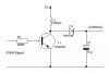
I want to boost 3V battery to 12V/50mA. Attached a sketch. No need feedback loop much.Because the boosted voltage will apply for a very limited time like 5mS then after I turn off the boost driver. If it really really needed then I can add that too.PWM driven from a PIC micro.

Need to confirm what frequency & what component values needed to make it boost to 12V/50mA from a 3V cell ?

Thanks
 

Attachments

  • boost.JPG
    boost.JPG
    14.9 KB · Views: 289
upload_2017-11-20_11-20-22.jpeg

The output voltage can not get below 2.4V. Power will flow from 3V through D1 and charge up C1. (even if T1 is removed)
When T1=on, current ramps up in L1.
I=3V X time/100uH. 3V is actually 2.8V because T1 will have some loss.
When T1 first opens up, energy stored on L1 will push up into C1. (C1 voltage can get too high with out a load)
3V will charge up 100uH slowly. Lets say 3 clocks of the micro.
12-3=9V. With 9V across L1, it will discharge quickly. About 1 clock.

What is the fastest PWM signal you can make?
 

Attachments

  • upload_2017-11-20_11-16-25.jpeg
    upload_2017-11-20_11-16-25.jpeg
    14.9 KB · Views: 353
Hi. Actually I'm going to use the inbuilt hardware module.
Pwm period=(PR2+1)*Tosc*Pre scale
By loading pr2=9, Tosc =1/4,Prescale=1:1 can get 100Khz.
 
An output current of 50 mA with a 4:1 voltage boost means that the transistor collector current will be at least 200 mA. For hard, fast saturation you will need to supply around 15-20 mA of base current.

ak
 
Actually I don't know how to get to the desired voltage, What frequency to drive etc....!! To change voltage do I need to adjust duty cycle?
 
Hi,

I simulated the circuit.Feeding a 100Khz PWM pulse width a 70% duty I managed to get closer to 12V. Without that load resister the voltage is rising. Is there any method to eliminate?
 

Attachments

  • Boost12v.png
    Boost12v.png
    23.2 KB · Views: 180
This supply is very dependent on load.
I would set the PWM to 1 count on and 255 off. See what happens.
Then set the PWM to 2 counts on, 3 on, 4 on etc.
At some point you will hit 12 volts.
Depending on what mode you are in it might take 3/4 on.
 
Unless you really just want to roll your own, I would go with something like this for $1.64 ...
**broken link removed**

I use this "gem" to supply adequate gate drive voltage to a mosfet under conditions where supply voltage could sag due to current loading.
 
The attached RF transmitter is my load. In standby mode it does not take any currents according to its datasheet...!!!

This is my only problem.
If I connect this to my boost converter will the output voltage rise above 12V? Any precaution to avoid that?
 

Attachments

  • RF.PNG
    RF.PNG
    120.9 KB · Views: 148
will the output voltage rise above 12V?
upload_2017-11-21_20-47-17.png

From post #10.
You need to measure the 12 volt supply many times a second and adjust the duty cycle. If you can not do that use a IC some thing like a LM27313. Just makes 12V. You can use /SHDN to stop the part. If not used, short R3 (remove).
 
You can replace a 9v battery with this circuit.
The output is about 10.4v on no load and 9.6v @30mA .
The advantage is the voltage stays over 9v for the life of the cells.
A normal 9v battery drops to 7v very quickly.
The output voltage is set to 9-10v by the 6k8 and 390R resistors. The 470R gives the circuit an idling current of about 20mA and the spikes are about 75mV.
By increasing the 470R, the quiescent current decreases but the voltage drops more when the current is 30mA.
9vRegulatedSupply.gif
 
Status
Not open for further replies.

Latest threads

New Articles From Microcontroller Tips

Back
Top