Continue to Site

Welcome to our site!

Electro Tech is an online community (with over 170,000 members) who enjoy talking about and building electronic circuits, projects and gadgets. To participate you need to register. Registration is free. Click here to register now.

  • Welcome to our site! Electro Tech is an online community (with over 170,000 members) who enjoy talking about and building electronic circuits, projects and gadgets. To participate you need to register. Registration is free. Click here to register now.

3V DC Motor, MOSFET Driver review?

Status
Not open for further replies.

shimniok

Member
Thanks in advance for your time. I'm a hobbyist, CompE degree from '93. I am interested in selecting a complimentary power MOSFET IC -- in h-bridge config -- to drive a 3V hobby motor via Microcontroller.

Hopefully someone can check my selection process. I've spent some time reviewing Sedra & Smith, looking at a few websites on motor drivers and mosfets, and reading a couple of app notes explaining MOSFET datasheet curves.

At this point, I am looking for input on my in-development heuristic for selecting an appropriate MOSFET given battery and motor specifications.

Motor: let's pick this Mabuchi FA-30-RA-18100 hobby motor for sake of argument. 2.1A stall current, 0.56A max efficiency. 1.5V - 3.0V DC operating range.

Power Supply: Also, let's say I am going to use 2 x AA alkaline batteries (as I understand, 3.0V charged, 2.0V depleted). Microcontroller will run off 1.8V-5.5V. So logic level out will range from 2V - 3V.

I'd like to keep parts count down, so driving gate directly from MCU is preferred over using MOSFET driver. I'd like to permit either PWM or continuous. I would run a fairly low PWM frequency (my thinking being that it would, I hope, reduce gate capacitance current draw? and make gate charge/capacitance issues less important in selection?)

My heuristic so far is...

1. Find MOSFETS rated well over 2A for N and P and Vgs(th) comfortably less than 2V.
2. Of those, look for MOSFETs with Id / Vds curves such that MOSFET will operate in triode region for expected operating current and voltage.
3. Of those, look for MOSFETs with lowest Rds(on) at the desired operating range.

Example... after sifting through various options and learning my best how to read the various curves... I come up with one possibility (of several)

On Semi, NTHD3102C (Datasheet, pdf) Images below reproduced for educational purposes.

Basic ratings are Vgs(th) = 1.2V; 4A (N), 5.5A < 5sec; 3.1A (P), 4.2A < 5 sec. So given a stall current of about 2A this should be entirely adequate. (and even drive other motors with higher stall current).

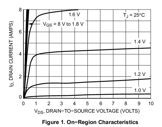
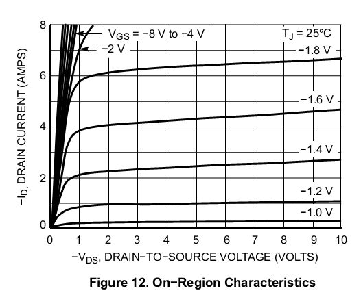
The Id vs Vds curve shows that at Vgs = 2V and up, the N and P MOSFETS should be in triode region for Id=2A with Vds < 0.5Ω

NTHD3102C_Id_Vds_N.jpg
NTHD3102C_Id_Vds_P.jpg


Unfortunately the datasheet doesn't show a Vgs vs Rds(on) curves as do the Vishay sheets I've looked at. Seems like that would be helpful.

However, if I look at the Id vs Rds(ON) for N and P it looks like the operating point will have Rds(on) at the low end of the scale.

NTHD3102C_Vgs_Id_N.jpg
NTHD3102C_Vgs_Id_P.jpg


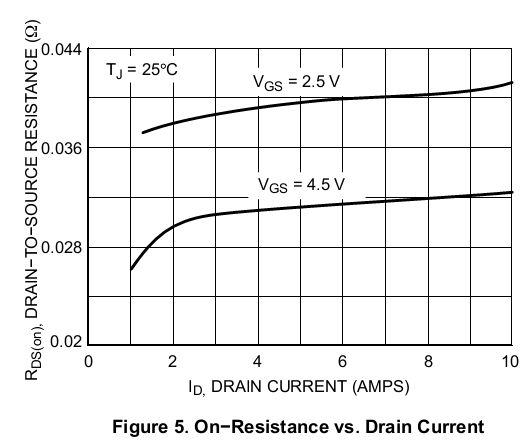
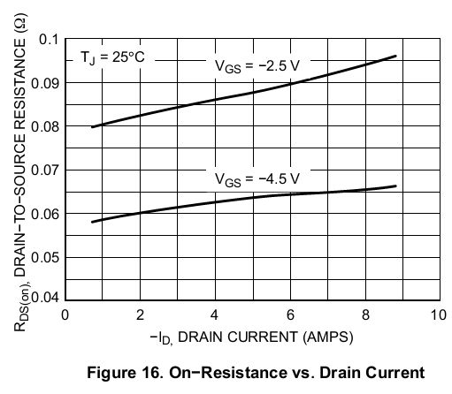
I see an Rds(on) vs Id for Vgs=2.5V and various Tj values. The Rds(on) values all look tiny to me.

NTHD3102C_RdsOn_Tj_N.jpg


NTHD3102C_RdsOn_Tj_P.jpg


On characteristics section shows Rds(ON) of -- guessing based on numbers -- of probably < 100mΩ for 2V / Id=2A.

What other charts should I consider?

Again thanks for your patience and time and help.

Michael
 
Hi Shimniok (Michael), I thought your name looked familiar, I had come across your robot website some time ago. :)

Re your mosfet, although this is not exactly what you asked for, it might be worth checking out the Pololu.com small motor drivers. They make a small cheap carrier board ideal for 3v DC motors and it directly accepts logic level inputs. They also sell the SMD chip (and the chip is cheap in bulk from other suppliers) if you wanted to use on your own design PCB. A ready made hbridge chip would be MUCH easier to use and smaller in hardware than trying to "roll your own". :)
 
@Mr RB -- thanks, saw those Pololu units and the associated chips. Definitely easier!

But... I'm hoping to drop the cost versus using the chip solution, hence the desire for using complimentary mosfet packages.

Also, it bugs me that I don't know how to roll my own MOSFET h-bridge. :D

I'm going to need to know how for another project later anyway. It's a personal challenge to figure out the MOSFET thing.

I gather that selecting mosfets for low voltage motor h-bridges isn't common knowledge since you're the only one that's responded so far. :D

I have selected a half dozen candidates and will likely just get a couple of the top contenders and just see if they work or not.

I can do some testing during normal run vs stall. Check temps, Vds, maybe current, and rpms if I feel ambitious, and form my own conclusions from that. I will attempt to predict behavior from the datasheet and try to find out if I'm right or wrong. Not sure what else I can do at this point.
 
Yeah I think may have scared off some people with a long post and lots of charts. Always funny to see when the main complaint people have is when someone posts a question without providing adequate information! ;)

I don't think you have too much to worry about with the mosfet choice, as those hobby 3v motors are low voltage (obviously) and also usually quite low current maybe 50-200mA. Its VERY rare to see current >1A on a 3v hobby motor unless it's a high perf RC racing type motor, most small 3v motors have stall currents well under 0.5A and usually less.

Your charts don't look so bad with that Rds on for 3v Vgs. If you drive the FET gates from a 3v micro CMOS output it will go pretty much from 0v to the full Vdd 3v, which makes the hbridge a LOT easier to design, especially since you can manually control PWM dead time with the micro.

The main thing to look for would be a "logic level" FET so it will turn on well with a low voltage to the gate, and maybe look for FETs that come in NFET and matching PFET types, which should be easy enough in a 2A low voltage FET.

If you are prepared to use 4 micro outputs to drive the 4 FETs in a hbridge and some code skills I think your job will be very easy. :)

Just keep in mind that a $3 chip can be cheaper and easier than 8 fiddly FETs, especially if you factor in board size and parts assembly/placement costs etc. And the IC has more features like current protect, and will be easier to drive from the micro.
 
Last edited:
@shimniok
On Semi, NTHD3102C (Datasheet, pdf) Images below reproduced for educational purposes.
Wow that's a tiny smt package (1206). Really low gate capacitance, so should be able to drive easily from a micro pin. Definitely worth a look/try. If PWM is really in the mix? then start with a high gear reduction or more battery.
 
Wow that's a tiny smt package (1206).

So, I decided I stand NO chance of soldering an 8-pin 1206-sized device, hot air rework station or no. :D I've pruned choices down to SOIC and TSOP devices.

Yeah I think may have scared off some people with a long post and lots of charts. Always funny to see when the main complaint people have is when someone posts a question without providing adequate information! ;)

No doubt. This thread would be on fire if I posted something like "make me a motor driver" and left it at that :D

I don't think you have too much to worry about with the mosfet choice...

Good to know. Sounds like my choices will be ok. I selected a couple used on the Pololu Orangutan LV-168, and another couple with lower Vgs(th) and "better" Ids/Vds curves.

YIf you are prepared to use 4 micro outputs to drive the 4 FETs in a hbridge and some code skills I think your job will be very easy. :)

Well... I was thinking 2... Borrowing from the LV168 design. Tie N and P gates together on each side and drive each with an MCU pin.

YJust keep in mind that a $3 chip can be cheaper and easier than 8 fiddly FETs, especially if you factor in board size and parts assembly/placement costs etc. And the IC has more features like current protect, and will be easier to drive from the micro.

Duly noted.

So the project I'm working on is a design contest to build a $10 robot -- umm... it's ok for me to ask for guidance on specific areas, I hope?! I had planned to cite whatever sources I used. I also am going to open source the whole thing so others can build it too.

I don't think I stand any chance of winning, but it's good motivation since I want to build a cheap robot platform as the basis for local classes I want to start hosting.

Anyway, a $10 price point for an autonomous programmable robot is rather ambitious so that's why I'm interested in saving even $.50 here or there even if it means giving up some niceties. The price difference between "raw" FETs and driver ICs is more like $1.50.

Thanks for the guidance !!

Michael
 
Well... I was thinking 2... Borrowing from the LV168 design. Tie N and P gates together on each side and drive each with an MCU pin.

That might be a problem. If the mosfets conduct at the same time they will be fried. The fact that you are driving the mosfet gates directly from MCU pin makes things even worse because the pin can't source much current.. this makes the switching action relatively slow.

I think you might like this paper: https://www.electro-tech-online.com/custompdfs/2012/08/slup169.pdf
 
I would run a fairly low PWM frequency (my thinking being that it would, I hope, reduce gate capacitance current draw? and make gate charge/capacitance issues less important in selection?)

PWM frequency is a trade-off between switching losses and motor efficiency. Low PWM frequency reduces switching losses because there is less switching.. of course. But it increases ripple current in the motor windings and that is waste of energy in the motor. The wasted energy heats up the motor.

Low PWM does not reduce gate capacitance current draw during one switch. It only reduces the average current over time. You want very low gate capacitance regardless of PWM frequency. Low capacitance means faster switching and therefore reduces switching losses.. and charging the gate is only a small part of it.
 
Last edited:
To add to the good advice from MisterT; the problem of "shoot though" will be an issue if you try to drive both P and N fet from one micro pin. There is also the issue of PWM, and what type of current recirculation you want (fast decay or slow decay etc) which are all available options if you use 4 pins to control the 4 FETs.

I disagree somewhat regarding the issue of gate capacitance and driving the gate directly from the micro CMOS output pin. You can get quite good motor driver results with PWM as low as a few hundred Hz, there is no need to go ultrasonic. But even at 20kHz the gate voltage is quite small so the capacitance is less of an issue and modern high perf microFETs like the ones you are looking at will switch quite fast when driven from a push-pull CMOS output pin. It's not like you are making a high efficiency SMPS running the FETs at 250kHz!

I'd like to know more about the $10 robot competition if you don't mind. Is this a kit people have to build or is the goal to make a pre-assembled robot? I'm still thinking that with 8 FETs and the PCB real estate and the SMD placement charges and setup fees it's going to add up. With a single chip it could be kit form, and the user can solder it. Toshiba and TI and probably other makers all offer some small low cost dual motor driver chips, they are very cheap in large quantities as they use them in things like digital cameras for the zoom motors etc. If the robot is a pre-assembled unit then to make the SMT affordable you might be looking at quantities of a few thousand anyway.
 
You can get quite good motor driver results with PWM as low as a few hundred Hz, there is no need to go ultrasonic.

Yes, particularly when driving cheap motors without feedback control. But all motors will run cooler (more efficiently) using higher PWM frequency.

But even at 20kHz the gate voltage is quite small so the capacitance is less of an issue and modern high perf microFETs like the ones you are looking at will switch quite fast when driven from a push-pull CMOS output pin. It's not like you are making a high efficiency SMPS running the FETs at 250kHz!

True, optimizing switching speed is important only with very fast PWM applications. Motor control is not one of them.
 
To add to the good advice from MisterT; the problem of "shoot though" will be an issue if you try to drive both P and N fet from one micro pin. There is also the issue of PWM, and what type of current recirculation you want (fast decay or slow decay etc) which are all available options if you use 4 pins to control the 4 FETs.

Thanks both of you for this great input. Really appreciate it.

I found some info on the topics in an engineering paper someone wrote up (hbridge-reference-ualberta-arvp.pdf)

I disagree somewhat regarding the issue of gate capacitance and driving the gate directly from the micro CMOS output pin.

Ok, time to go check the datasheets. :)

I'd like to know more about the $10 robot competition if you don't mind. Is this a kit people have to build or is the goal to make a pre-assembled robot?

Sure! Maybe you guys should give it a go? It's put on by the African Robotic Network (AFRON). Here's the link: **broken link removed**

The goal is to build a robot for primary/secondary education in developing countries cheaply enough to make it feasible. For that matter, these could be used in any country.

There are three classes for entry. I'm aiming for the traditional class, where the programmer/interface is on a laptop. I believe it can either be fully assembled, partial kit, or full kit form. I'm likely going for partial kit / fully assembled options.

The goal is $10 but they accept any design < $100. I'm trying to come up with a design as close to $10 in parts as I can. Didn't consider assembly costs. Oops.

Also they encourage you to work out the volume costs.

I'm still thinking that with 8 FETs and the PCB real estate and the SMD placement charges and setup fees it's going to add up.

Ok, so having never actually gone through the manufacturing process, I have no idea how the pricing works. I guess it makes sense that there'd be a setup fee and a per-part cost. There's a PCB fab house locally that does assembly too. I guess I can see if they'd give me a quote when I narrow in on a couple of candidate designs.

My design is almost certainly going to have a single drive motor. So that's only 2 ICs if I use the 4-pin MCU-driven approach. Otherwise I guess it would require lots of supporting hardware to drive the MOSFETs. Right now the PCB is < 2 in-sq with room for more stuff or else a need for me to compact it some more :)

If I go with all-in-one ICs, there are a few options like the Sanyo LB1836M, the Toshiba TB6612, the TI DRV8837, among others. For my prototype I can get the Toshiba in breakout board form from Pololu, but the DRV8837 would probably be a challenge for me to populate.

The LB1836 comes in SOIC form so I can hand populate that easily. A 2x3mm DFN, or 1206 8-pin ChipFET not so much. :)

Also, though I would like to, I doubt I can get boards to me in time. I will probably have to prototype on a breadboard or etch my own board (I can get down to 16 mil traces reliably, anything smaller is pushing it; TSSOP is doable but barely). I know a place that does really fast turnaround but probably too expensive for my meager hobby budget. I'll have to go look.

Michael
 
Status
Not open for further replies.

Latest threads

New Articles From Microcontroller Tips

Back
Top