Continue to Site

Welcome to our site!

Electro Tech is an online community (with over 170,000 members) who enjoy talking about and building electronic circuits, projects and gadgets. To participate you need to register. Registration is free. Click here to register now.

  • Welcome to our site! Electro Tech is an online community (with over 170,000 members) who enjoy talking about and building electronic circuits, projects and gadgets. To participate you need to register. Registration is free. Click here to register now.

300W Adjustable / constant current discharger (again?)

Status
Not open for further replies.
I don't see how in the posted schematic it balances the load current.

As I said above, they are inherently self-balancing - AS LONG AS YOU CHOOSE THE CORRECT DEVICES - I've no idea if the specific ones mentioned are or not. But as long as Rds increases as the device gets warmer, then they will balance - just as balancing resistors work. If you choose to use devices where Rds decreases as it gets warmer, then you MUST use balancing resistors.

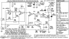
However, as it's a circuit just 'scribbled' on apiece of paper, you never know what might or might not be used - if in doubt stick a low value resistor (0.1ohm?) in each source connection.
 
..................................
I'd been helping Tim outside of the forum with another project and he found this design for a CC load.

https://ianjohnston.com/images/stories/IanJ/DummyLoad2/schematic.JPG

When I looked at it I can't see how it balances the load between the two MOSFETs. I know that the specific MOSFETs shown are designed for linear power operation with extended FBSOA (and very expensive). However without individual ballast resistors in the source circuit of each MOSFET and the gates connected together, if one MOSFET carries more current, it gets hotter, its Rds goes up, so the current drops, but the constant current feedback drives the gates harder to try and bring the current back up.

I'd be interested to know if I've got the operation correct and it doesn't really balance the load or I've misunderstood how it is working. The guy who designed it is clearly very good based on the other projects on his website so I'm thinking I've not understood it.
.....................
The two MOSFETs would need to have matched threshold voltages (Vgs(th)) for that scheme to give balanced currents. Since threshold voltages normally have significant variation between units, two arbitrarily selected MOSFETs will likely mean one will hog most of the current. Two MOSFETs only balance well if they are being used as full-on as switches, where the threshold voltage variation has little effect.
 
Last edited:
@ crutschow ---- nice solution.
Can you run the simm. with a Vbatt dropping from 12.7V to 7V?
Why would you want to go to such a low voltage? That is well below the recommended minimum discharge voltage of any lead-acid battery and could damage it.

If the battery voltage dropped to 7V then the maximum control input voltage would be about 2.5V (giving 5V across the load resistors). Otherwise the circuit would work the same except that the MOSFET power dissipation would be a lot higher for a given current when the battery voltage is 12V.
 
..........................
Also, it seems the MOSFET mentioned is a surface mount device, but I may be looking at the incorrect variant?
..............................
I just chose an arbitrary MOSFET in my simulation library and didn't look at its package. For this design you would need a MOSFET with a case that can handle the power when bolted on a large heat-sink, and obviously a surface-mount package is not appropriate for that. ;)
 
When using multiple FETs in parallel for this application each needs it's own op amp and load resistor. Add a 100 ohms in the gate to prevent oscillations.
 
Thanks for that (and the update). I must admit I don't fully understand the circuit diagram when presented like that and for my simple head. ;-(
,,,,,,,,,,,,,,,,,,,,,,,,,,,,,,,,,,,,,,,,,,
An op amp with negative feedback will attempt to adjust it's output voltage to keep the voltage difference between its two inputs close ot 0V.
Here the op amp uses this negative voltage feedback from the load resistors to control the MOSFET gate voltage and maintain the voltage across the load resistors equal to twice the input control voltage (due to the divider network R2 and R3 reducing the resistor voltage by 1/2 at the op amp input).
Because of this negative feedback and the isolation effect of the MOSFET drain, the current is basically independent of the battery voltage (as long as the voltage doesn't drop below the set resistor voltage) and equals 1/2 Vcntl divided by the equivalent load resistance.

That help any?
 
I'm not sure how you could with a constant current load? - as it bears no relation to reality.

The only way to do it accurately is to do it with the exact load that it's going to be used with, as it will vary considerably depending on the exact load conditions.

Since the capacity of a battery is measured in AmpHours, using a constant current load makes calculating the results very easy.

LoadCurrent * runtime(in hours) = battery capacity. You only need to measure the voltage to know when to shut off the discharge.

If you use a restive load, you'll need to measure and integrate a constantly changing current.
 
When using multiple FETs in parallel for this application each needs it's own op amp and load resistor. Add a 100 ohms in the gate to prevent oscillations.

Absolutely correct. Figure 4 in the IXYS link in post #20 shows such a circuit.
 
Since the capacity of a battery is measured in AmpHours, using a constant current load makes calculating the results very easy.

But gives a figure with no relation to actual usage - real life doesn't draw constant currents.

LoadCurrent * runtime(in hours) = battery capacity. You only need to measure the voltage to know when to shut off the discharge.

If you use a restive load, you'll need to measure and integrate a constantly changing current.

Which is trivial to do, as you're using a processor :D
 
This Circuit will give you a Constant Current Output.
But I would Recommend a Higher Current Mosfet.
Possibly a "STP75NF75".
The "Load" can be Eliminated, so it will Sink the battery direct to ground.
Or it could be a Low Resistance of about 0.2 Ohms.

The Wire "R12" Needs to be able to handle the Total Current.
 

Attachments

  • I-Limit-PWM-1.PNG
    I-Limit-PWM-1.PNG
    21.5 KB · Views: 337
Last edited:
As I re-read the first post, it seems clear to me that the OP is looking to measure the capacity of a battery, not runtime with a particular device. The industry standard unit of measure for stating battery capacity is the AmpHour. And the easiest way to measure that, is with a constant discharge current. Certainly not the only way, just the easiest.

As for constant current loads, I can suggest a common circuit configuration that will be constant current. If you had a circuit that drew relatively constant power, and you were using a linear voltage regulator to power it from a 12 volt battery, it would look to the battery as a constant current load. The power dissipation of the regulator would decline as the battery voltage does, but the input current wouldn't change.
 
This is interesting...
Perhaps the OP should have a look at this item:
https://www.electro-tech-online.com...ester-logger-for-12v-lead-acid-batteries.673/

I've been happily using it for a few months. It doesn't do constant current (although it could with a software mod) and it can be easily expanded to do whatever wattage u require, no heatsinks or fans required. This model goes up to around 10Amps. The load is 'digital PWM' at 7.8Khz.

It does the datalogging etc. and calcs the AH based on the Ah discharged by sampling continuously (integration in dig. form).

It exists as a complete kit at clubjameco.com if you don't want to build it from scratch.

If you need anything particular in the design , lemme know.

BTW...somehow Nigel always seems to have thought up the approach I eventually end up using. Noting post # 6....with a bulb as a load. That also works great cuz u can see from quite a distance when the discharge is complete.
 
Last edited:
Status
Not open for further replies.

Latest threads

Back
Top