Continue to Site

Welcome to our site!

Electro Tech is an online community (with over 170,000 members) who enjoy talking about and building electronic circuits, projects and gadgets. To participate you need to register. Registration is free. Click here to register now.

  • Welcome to our site! Electro Tech is an online community (with over 170,000 members) who enjoy talking about and building electronic circuits, projects and gadgets. To participate you need to register. Registration is free. Click here to register now.

2nd Power Supply

Status
Not open for further replies.

mark_3094

New Member
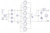
I've created a second power supply (the schematic attached) using a variable voltage regulator.

All works well in theory. I have a volt meter as part of the circuit, and it's reading goes up and down as I turn the pot. I also have an ammeter connected.

However, there is a really fundamental problem that I have overlooked somewhere. When I attach a small DC motor to the output, the voltage drops to zero, and the current goes up a little.

There must be some really simple principle or law I'm overlooking, but I'm not that experienced, so I can't see what it is.

PS, I didn't have this problem with a fixed voltage, using a 7809 regulator that I posted in a previous thread.


Thanks anyone who can enlighten me on this...
 

Attachments

  • Variable Power Supply Schematic.jpg
    Variable Power Supply Schematic.jpg
    38.9 KB · Views: 999
Please provide a link to the other thread. There are 1000s o threads in this forum, I don't know which one you're talking about.

For a start R2 is much too high, it should be 120R otherwise it won't regulate properly under light loads. The LED will help you at higher output voltages but it won't draw the minimum load current at lower voltage settings.

R1 might also be too low for the LED, it'll allow about 33mA to flow which will probably exceed the maximum rating of the LED.

C1 is far too small, for 1.5A it should be at least 1500µF though I'd recommend 2200µF.

What's the current rating of the motor?

It could be overloading the regulator.

Are you using a suitable heatsink?
 
Last edited:
hi Mark,
Im running out of ways to say this..

The smoothing capacitors on the input and output of the regulator or NOT adequate.. 1000uF and about 470uF are required.
 
This is the other thread:
https://www.electro-tech-online.com/threads/power-supply.91484/

The datasheet says that R2 can be 240R. I thought this could be changed (to change the ratio of R1 and VR1). I'll change it back to 240R

I'll change the resistors and caps at some point and see how that goes.

If the regulator overheats, will it start again as soon as the excess load has been removed? I'll put on a good heatsink and see how that goes too.

I'm not sure what the current rating of the motor is, but it's only small, so it wouldn't be 1A. It does run from a 9V battery, so it can't be too high.

I did find that if I turned the voltage up, R2 would burn out. It's power rating must be too low.

If P=IV, and the circuit can provide up to 1A at a max of 27V, does that mean the resistor must be 27W? That sounds really huge... Have I got that wrong?
 
The datasheet says that R2 can be 240R.
Correct. But not for an LM317. 240 ohms can be used for the more expensive LM117.

If the regulator overheats, will it start again as soon as the excess load has been removed?
Yes but the thermal stress of heating and cooling over and over will shorten its life.

I did find that if I turned the voltage up, R2 would burn out. It's power rating must be too low.
If your circuit is connected correctly then the current in the pot is only 5mA which will not burn it.

If P=IV, and the circuit can provide up to 1A at a max of 27V, does that mean the resistor must be 27W? That sounds really huge... Have I got that wrong?
You are talking about the load. It has up to 27V at up to 1A which is 27W.
The pot will have a max voltage of 25.75V at 5mA which is a power of only 0.129W. Isn't it a 1/2W pot? The pot will dissipate more than 1/2W if you use the correct value for R1 for an LM317.
 
Using the LM317 I found that it was hard to get an accurate output.
Would it be good to use multiple LMxx rectifiers with a switch?
Or one 'large' rectifier like the LM7818 and have voltage dividers running off it? Would the voltage dividers cause the voltage to be inaccurate too?

I have included a conceptual schematic of the multiple rectifier design...
 

Attachments

  • Selectable Power Supply Schematic.jpg
    Selectable Power Supply Schematic.jpg
    55.2 KB · Views: 242
Using the LM317 I found that it was hard to get an accurate output.
Would it be good to use multiple LMxx rectifiers with a switch?
Or one 'large' rectifier like the LM7818 and have voltage dividers running off it? Would the voltage dividers cause the voltage to be inaccurate too?

I have included a conceptual schematic of the multiple rectifier design...

hi Mark,
I think you mean multiple regulator design

What would be the point of this design, only one Vreg would be selected at anyone time.?

Voltage dividers will not give a stable voltage under different load conditions.

When you say 'I cant get an accurate output' what type of adjustment control are you using.?

The 24Vac transformer voltage when rectified will give a Vdc of about 33V peak, the regulators will run hot.
 
Last edited:
This is the other thread:
https://www.electro-tech-online.com/threads/power-supply.91484/

The datasheet says that R2 can be 240R. I thought this could be changed (to change the ratio of R1 and VR1). I'll change it back to 240R

I'll change the resistors and caps at some point and see how that goes.

If the regulator overheats, will it start again as soon as the excess load has been removed? I'll put on a good heatsink and see how that goes too.

I'm not sure what the current rating of the motor is, but it's only small, so it wouldn't be 1A. It does run from a 9V battery, so it can't be too high.

I did find that if I turned the voltage up, R2 would burn out. It's power rating must be too low.

If P=IV, and the circuit can provide up to 1A at a max of 27V, does that mean the resistor must be 27W? That sounds really huge... Have I got that wrong?
as you have a potentiometer in the circuit, and you did not intimate the output voltage, it is difficult to answer. now you say that you tested a motor with 9V, should we take it as 9V DC output ?

if that be the case, and with 24V secondary of transformer, the difference between input and output is much. unregulated DC would be less than (24*√2)-1.4Volts, say 30V. output is 9V. at 1.5amps load, the regulator needs to absorb 21V*1.5A=approx 30 watts.
did you provide a GOOD and big heat sink? other wise it would shutdown due to thermal shut down behavior.
as Eric suggested, you need a higher Electrolytic at the output in addition to a 0.1uF ceramic cap.
 
Yes, you're right, Multiple regulator design.

I only want to have one voltage output at a time, but I want it to be selectable. So I can turn it to 9v for one project, 5v for another, etc...

The inaccurate output is like this:
I was using the LM317 with the voltage divider (one regular resistor and one pot) on the common pin as shown in the data sheet.
I wired up a simple 555 LED flasher as a 'load' to test the circuit. With no load, I turned the pot up to 9v.
The volt meter needle was not staying steady at 9v, but was jumping around a bit. When I use the LM7809 with the common pin grounded, the needle on the volt meter stays steady on 9v, while the needle on the amp meter jumps with every flash.
That's why I was thinking of using multiple regulators.

Yes, heat will be a big problem. I will of course need to have big heatsinks on each regulator. Perhaps I could use a multitap transformer so the 'smaller' regulators won't have to deal with as much voltage?

The other reason that I don't want to go with the LM317 is because it would be more open to user error. I could accidentally turn it to 10v instead of 9v by mistake, whereas a rotary switch would 'click' into place.
Perhaps you did not think over the issue that 317 can also be configured with a set of pre selected Resistors and switchable so that errors cant creep in, instead of a potentiometer.
 
The thought did cross my mind...
But how accurate would it be? Would I need low tolerance resistors for it to be accurate enough?
Would it still get really hot if it's turned down (eg, 3v or 5v)?
Would a heatsink like the one in the top right of this PDF be good enough? Would I need a small fan?

https://www.electro-tech-online.com/custompdfs/2009/04/heatsink-1.pdf

hi,
One reason the voltage on the output dips is due to the output capacitor being to low a value, use a 470uF or 1000uF for motors.

The LM317 can be set to switched outputs by using small pots so set each voltage on the switch.

With that high voltage input from the rectifier the medium and low voltage settings will make the reg hot on low/medium currents.

EDIT:
another point you should consider is the resistance of the ammeter, its in series with load.
 
Last edited:
hi,
One reason the voltage on the output dips is due to the output capacitor being to low a value, use a 470uF or 1000uF for motors.

The LM317 can be set to switched outputs by using small pots so set each voltage on the switch.

With that high voltage input from the rectifier the medium and low voltage settings will make the reg hot on low/medium currents.

EDIT:
another point you should consider is the resistance of the ammeter, its in series with load.
Better concept than searching for independent resistors of selected special values.
 
hi,
One reason the voltage on the output dips is due to the output capacitor being to low a value, use a 470uF or 1000uF for motors.
No.
A voltage regulator has excellent voltage regulation when it is wired correctly. An output capacitor larger than 10uF (tantalum) or 25uF (electrolytic) makes no difference. These little output capacitors improve the transient response.
The datasheet for the LM317 describes how a wire or pcb trace that measures only 0.05 ohms from the output of the LM317 to the voltage setting resistors makes the voltage regulation 11.5 times worse when the load current changes. This would occur if the regulator is made on a breadboard. The voltage regulation could be 100 times worse or more.

The output voltage of an LM317 set to 5.0V drops typically only 5mV when the output current is changed from 10mA to 1.5A.
If a 10uF capacitor is added from the ADJ terminal to ground and the input ripple is 2V p-p then the output ripple is typically only 0.2mV p-p (1mV p-p without the capacitor).
 
Last edited:
hi,
Yes.
It may in theory be a 10/25uF across the output of a regulator, but from my experience when driving motors/inductive etc, the LM317 will not hold the set output voltage.

Even though a motor draws 1amp while running, it can be far higher than 1.5A when starting and the regulated voltage dips, the LM317 is not fast enough and is not capable of delivering the higher load current directly.

This 'dip' can cause problems in any 'logic' type circuits that are on the same line.
I would fit a miniumum of 470uF when building a psu for general purpose projects.
 
Last edited:
I have included a new conceptual idea for a power supply. Unfortunately it is a little crude, so I will explain it here.

The idea of this one is to have the LM317 with trimpots to adjust the voltage.

A rotary switch is used to select the voltage.

There is a transistor (used as a switch) with the base connected to the rotary switch. The emitter goes to the bridge rectifier, but the collector goes to a multitap transformer.

Although not shown very well on the schematic, the collector of each transistor has a different voltage from the transformer. The reason for this is so there is less voltage going into the voltage regulator when it has a low output.

The less voltage in should mean that it does not have to dissipate as much heat, and the risk of burning out is much lower. It will still have a heatsink.

I haven't worked out the details on the transistors yet.


Will this work?
 

Attachments

  • Variable Power Supply Schematic.jpg
    Variable Power Supply Schematic.jpg
    86.6 KB · Views: 215
I have included a new conceptual idea for a power supply. Unfortunately it is a little crude, so I will explain it here.

The idea of this one is to have the LM317 with trimpots to adjust the voltage.

A rotary switch is used to select the voltage.

There is a transistor (used as a switch) with the base connected to the rotary switch. The emitter goes to the bridge rectifier, but the collector goes to a multitap transformer.

Although not shown very well on the schematic, the collector of each transistor has a different voltage from the transformer. The reason for this is so there is less voltage going into the voltage regulator when it has a low output.

The less voltage in should mean that it does not have to dissipate as much heat, and the risk of burning out is much lower. It will still have a heatsink.

I haven't worked out the details on the transistors yet.


Will this work?
It is wrong as you never got the DC bridge through properly and these switching transistors are shown connected at AC level. It should be like the attached modified schematic.
 

Attachments

  • Variable psu Mod.jpg
    Variable psu Mod.jpg
    71.9 KB · Views: 208
Last edited:
OK, I'll add the capacitor on the ADJ terminal, and the diode across OUT and IN terminals.

If the transistors are no good, is there any way I can make the input voltage selectable? I don't want to burn out the voltage regulator if I'm putting 18v or more into it, but only getting 1.5v out...


Thanks :)
 
Status
Not open for further replies.

Latest threads

New Articles From Microcontroller Tips

Back
Top