After (nearly) overheating my computer from running LTSpice simulations, I learned that a 0.1uH inductor wouldn't cut it for my needs, but a 22nH inductor will work since I am dealing with around 433Mhz.
I have looked on ebay for some and since I don't do smd, the others I found are air core and tuneable. Just by looking at air core I feel I could make one myself.
Since 22nH is such a small number, is there an equation I can use to calculate inductance if all I used to make the inductor is a flat piece of 22awg shielded (i think steel here since the wire color is silver) wire with maybe 5mm of shielding stripped off each end?
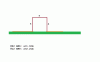
Once I know the perfect length, I will then make a U shape out of it and hook it onto the circuit board through-hole style.
I understand I can make one from a circuit board itself but I want to go against that option because if I need to change the inductor value later, its much cheaper for me to replace the wire with one of different size than to replace an entire circuit board.
I have looked on ebay for some and since I don't do smd, the others I found are air core and tuneable. Just by looking at air core I feel I could make one myself.
Since 22nH is such a small number, is there an equation I can use to calculate inductance if all I used to make the inductor is a flat piece of 22awg shielded (i think steel here since the wire color is silver) wire with maybe 5mm of shielding stripped off each end?
Once I know the perfect length, I will then make a U shape out of it and hook it onto the circuit board through-hole style.
I understand I can make one from a circuit board itself but I want to go against that option because if I need to change the inductor value later, its much cheaper for me to replace the wire with one of different size than to replace an entire circuit board.