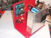
Here is a neat creation I built this week during a few evenings.
Its an adjustable 20 - 40 volt 5 amp SMPS for my brothers homemade CNC machine.
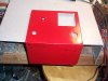
I used an old advance floor scrubber battery charger case and I just burned off all the old paint with the propane torch and hammered out the dents.I then used the die grinder and wire wheel to clean up the metal and lastly washed it down with starting fluid to remove the last bits of dirt.I then painted it with standard red Rustolium spray paint. I just used the cutoff wheel and cut a rectangular hole where the original round amp meter was and GB welded the old switch and fuse holes shut.
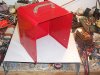
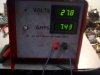
The face label is just a simple Auto Cad layout I came up with and then printed onto a large peel and stick shipping label.
I clear coated the label to make it more durable but once the clear coat saturated the label paper it gave it a sort of marbled look.
Not intentional but still it actually looks rather unique with it.")
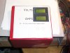
The displays are stock digital meters I got on eBay for about $9 each.
they are based on the standard ICL7106 A/D converter IC.
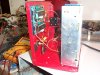
I just used silicone to hold them in place.
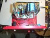
The voltmeter is stock and can read up to 200 volts. The Ammeter is a 200 volt unit that I took the voltage divider circuit out of so it would read 200 millivolts and changed the decimal point connection to move it over one place to the left. I used two .005 ohm 2 watt resistors in series on the negative return line to create the voltage reference for the amp meter.
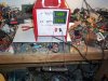
The actual power supply is an old commercial 24 VDC unit I pulled off some scraped out industrial equipment. It was originally rated for 100 - 140 VAC input with 24 V 3.5 amp and 5 v 2 amp outputs. The 5 volt side powers the digital readouts.
I changed the main switching FET from a stock 10 amp 500 volt to a 15 amp IRF450. The output diode was originally a dual 8 amp and I switched it with dual 15 amp. The output capacitors on the 24 volt were originally a pair of 2200 uf 35 volt. I changed them out with a 2200 uf 50 volt and a 4700 uf 50 volt.
The 24 volt regulation circuit is a standard LM431 shunt regulator type so I just changed the adjustment pot from a 1k to a 5k and changed the divider resistors to get the 20 - 40 volt output range. The original over voltage protection was set at 27 volts and would shut down the power supply. I added a second 15 volt zener in series with the original one to move the limit up to 42 volts.
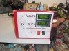
The overall performance was surprisingly good. It now can hold a 10 amp peak output for 30 seconds with less than a .7 volt drop from no load to overload across the full operating range.
The continuous capacity is 5 amps over the full range with a 7.5 amp extended load capacity only limited by the 5 amp circuit breaker trip out time of about 2 minutes. The voltage drop at 5 amps is about .4 volts.
Once calibrated the meters are within +- .1 volts and .05 amps in reference to my 4.5 digit digital meter.
I plan to get a 5K pot and mount it in the front face where that hole is next to the voltage meter. That way its externally adjustable.
Not to bad for under $20 in parts and some scavenged junk I had laying around!
Its an adjustable 20 - 40 volt 5 amp SMPS for my brothers homemade CNC machine.
I used an old advance floor scrubber battery charger case and I just burned off all the old paint with the propane torch and hammered out the dents.I then used the die grinder and wire wheel to clean up the metal and lastly washed it down with starting fluid to remove the last bits of dirt.I then painted it with standard red Rustolium spray paint. I just used the cutoff wheel and cut a rectangular hole where the original round amp meter was and GB welded the old switch and fuse holes shut.
The face label is just a simple Auto Cad layout I came up with and then printed onto a large peel and stick shipping label.
I clear coated the label to make it more durable but once the clear coat saturated the label paper it gave it a sort of marbled look.
Not intentional but still it actually looks rather unique with it.
The displays are stock digital meters I got on eBay for about $9 each.
they are based on the standard ICL7106 A/D converter IC.
I just used silicone to hold them in place.
The voltmeter is stock and can read up to 200 volts. The Ammeter is a 200 volt unit that I took the voltage divider circuit out of so it would read 200 millivolts and changed the decimal point connection to move it over one place to the left. I used two .005 ohm 2 watt resistors in series on the negative return line to create the voltage reference for the amp meter.
The actual power supply is an old commercial 24 VDC unit I pulled off some scraped out industrial equipment. It was originally rated for 100 - 140 VAC input with 24 V 3.5 amp and 5 v 2 amp outputs. The 5 volt side powers the digital readouts.
I changed the main switching FET from a stock 10 amp 500 volt to a 15 amp IRF450. The output diode was originally a dual 8 amp and I switched it with dual 15 amp. The output capacitors on the 24 volt were originally a pair of 2200 uf 35 volt. I changed them out with a 2200 uf 50 volt and a 4700 uf 50 volt.
The 24 volt regulation circuit is a standard LM431 shunt regulator type so I just changed the adjustment pot from a 1k to a 5k and changed the divider resistors to get the 20 - 40 volt output range. The original over voltage protection was set at 27 volts and would shut down the power supply. I added a second 15 volt zener in series with the original one to move the limit up to 42 volts.
The overall performance was surprisingly good. It now can hold a 10 amp peak output for 30 seconds with less than a .7 volt drop from no load to overload across the full operating range.
The continuous capacity is 5 amps over the full range with a 7.5 amp extended load capacity only limited by the 5 amp circuit breaker trip out time of about 2 minutes. The voltage drop at 5 amps is about .4 volts.
Once calibrated the meters are within +- .1 volts and .05 amps in reference to my 4.5 digit digital meter.
I plan to get a 5K pot and mount it in the front face where that hole is next to the voltage meter. That way its externally adjustable.
Not to bad for under $20 in parts and some scavenged junk I had laying around!
Attachments
-
 DCP01555.JPG235.6 KB · Views: 1,261
 -
 DCP01556.JPG303.1 KB · Views: 782
 -
 DCP01557.JPG198.8 KB · Views: 714
 -
 DCP01558.JPG332.2 KB · Views: 778
 -
 DCP01559.JPG269.6 KB · Views: 1,034
 -
 DCP01560.JPG308.3 KB · Views: 795
 -
 DCP01562.JPG305.9 KB · Views: 3,408
 -
 DCP01563.JPG319.3 KB · Views: 712
 -
 DCP01565.JPG197.2 KB · Views: 901
Last edited:

