camerart
Well-Known Member
Hi,
Here is a program on an 18F46K20 PIC
There is a LOOP around the START UP LEDS, which should flash ON/OFF 1/sec, the LEDs flash app 1 /4sec.
I've tried to set the timing registers, and notice to get 32MHz x4 is needed, then in T1CON BIT 1 the internal option divides by 4, which seems to defeat the object. The LEDs flash app 1 in 4sec
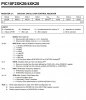
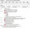
T1CON = %11111101 '7=16BIT, 6=TIMER1 osc 54=1:8, 3=EN OSC, 2=INT, 1=INT osc/4 0=En TMR1
T2CON = 0
T3CON = 0
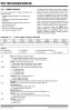
OSCCON = %01101110 '7=sleep 654=Osc frequency 8MHz 3=CONFIG1 REG 2=stable 10=INT OSC
OSCTUNE.PLLEN = 1 'OSCx4
Any ideas please?
Camerart.
Here is a program on an 18F46K20 PIC
There is a LOOP around the START UP LEDS, which should flash ON/OFF 1/sec, the LEDs flash app 1 /4sec.
I've tried to set the timing registers, and notice to get 32MHz x4 is needed, then in T1CON BIT 1 the internal option divides by 4, which seems to defeat the object. The LEDs flash app 1 in 4sec
T1CON = %11111101 '7=16BIT, 6=TIMER1 osc 54=1:8, 3=EN OSC, 2=INT, 1=INT osc/4 0=En TMR1
T2CON = 0
T3CON = 0
OSCCON = %01101110 '7=sleep 654=Osc frequency 8MHz 3=CONFIG1 REG 2=stable 10=INT OSC
OSCTUNE.PLLEN = 1 'OSCx4
Any ideas please?
Camerart.