Continue to Site

Welcome to our site!

Electro Tech is an online community (with over 170,000 members) who enjoy talking about and building electronic circuits, projects and gadgets. To participate you need to register. Registration is free. Click here to register now.

  • Welcome to our site! Electro Tech is an online community (with over 170,000 members) who enjoy talking about and building electronic circuits, projects and gadgets. To participate you need to register. Registration is free. Click here to register now.

18F2455 controlling relays

Status
Not open for further replies.

blinky465

New Member
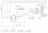
Hello. I've built a USB device which enumerates and is recognised by windows. I want to send a sequence of bytes to turn on up to 4 separate relays. Coding isn't an issue, but I'm struggling to understand why, if I have an output signal from the microcontroller to an LED connected to a transistor in parallel, the LED lights up but the relay (connected to the emitter pin3 of a BC517 transistor) does not switch over.

In the schematic, 5v has been added as a label to aid with PCB layout. There is no separate power supply, it is all from the diode connected to USB pin 1.
(I have double-checked that all diodes are connected the right way around!)
**broken link removed**

For example, when I send 5v output on RB3 (to turn on relay 4) the LED comes on but nothing happens with the relay. If I manually put 5v onto pin3 of the transistor, the relay does switch on with an audible click, so I know that the diode is connected the right way around!

Here is the PCB layout. The connector labelled "0" is simply a jumper connecting all of the transistors pin1 to 5v.
**broken link removed**

Can anyone offer any advice?
 
Transistor types are NPN?

In case it helps, the transistors used in the project (above) have part number BC517. Datasheets are available through Google: pin1 = collector, pin2= base, pin3=emitter
 
You have 2 diode drops between +5 and your relay one from the transistor and the other from the extra diode after the transistor, it might be too little voltage to switch the relay. What are D11-D14 for? They don't appear to serve any purpose but dropping more voltage (which is exactly what you don't want to do) If they're supposed to be flyback diodes they're supposed to go the other way around and be wired in parallel with the relay, not in series in the direction they currently are. How much current does the relay require? Replacing the transistors with logic level mosfets will give you much better drive to your relay from 5 volts, but if you get rid of your series diode it may work.
 
Last edited:
What are D11-D14 for? If they're supposed to be flyback diodes they're supposed to go the other way around and be wired in parallel with the relay, not in series in the direction they currently are.

I'm not familiar with the term flyback diode, but I guess that's what I was aiming at - they're to stop any stray voltage making its way back to the micro when the relay coil turns off again (back emf?)
If they're left out, would back-emf be a problem when the relay goes from an "on" back to "off" state?
 
Thanks Sceadwian

Thanks for the advice - you're absolutely right - if I bridge the diodes D11-D14 (effectively remove them) then putting 5v onto pin2 does indeed switch the relay on! With that in mind, if I replace these diodes with jumpers (to make the PCB layout easier) how do I protect my pic micro when the relays are no longer energised?
Thanks again!
 
Put the diodes in parallel with the relay coils, that stops the back emf. Then replace D6 with a 10 ohm resistor, and put a bit cap 470uF or larger for the relay power, ie from pins 1 of the transistors to the relay ground.
 
It's too bad that you've already built the PCB. The real solution is to put the relay coils in the collector circuit of the transistors.
With the diodes bypassed and the relays energized, what is the voltage across the coils? Even with the extra voltage you gained by eliminating the diode voltage drops, the relay actuation may not be 100% reliable due to the Vbe drop of the transistors and the fact that the PIC won't put out the full 5V while also driving the LEDs.
You should also have a 0.1uF bypass cap across the supply leads of the PIC.
 
Last edited:
Make sure you turn the diodes around!!!! They'll short the 5 volt supply to ground if you don't turn them the other way around. That way when the relay turns off the voltage on the relay will reverse, but it will be able to flow through the diode, eliminating the voltage spike that would otherwise occur. They're called flyback or freewheeling diodes commonly.
 
kchristie, is right though part of the problem may be the position of the relays, they should be on the collector side and then you ground the emitter, the relay has a DC resistance which will provide feedback which may make the base current much less than it would be if it was simply gruonded. You're using a darlington so it MAY not be enough to cause it to not switch but you'd get better performance kchristies way.

If you do change the PCB so the relays are on the other side though you'll need a base resistor to keep the current from the PIC from getting too high.
 
Last edited:
Revision 2

Thanks to everyone who has offered help - it all makes sense. I didn't think about voltage drop across each of the components (eg diodes and transistors) and why switching on the relay 0v side would be a better way of doing things!

Here's the revised schematic. I'll work out resistor values for R11-R14 once I know the minimum operating current for the relay coils. Should this revised layout offer sufficient protection as my relays go clitter-clatter?

**broken link removed**
 
Third time lucky?

Again, it makes sense when I see it - I'm just thankful that you guys are so patient, forgiving even the simplest of mistakes! Does this schematic nail it?

**broken link removed**
 
Perhaps too late for this project - but would suggest you look at the ULN2803A octal relay driver chip, its a lot easier to use than separate transistors,resistors and diodes - you can connect the pic directly to its inputs and the relays straight to the outputs - the chip contains all the diodes - so no other components needed.

You should still remove D6 as mentioned eariler, don't know what D7 to ra1 is for.

If your project is for anthing critical, then you might find, as I have done on a couple of occassions, that powering it from USB can cause problems with unexplained program errors etc - basically caused by the poor power regulation / noise of the usb rail.
Supplying it from a powered usb hub or separate psu would be better
 
Last edited:
You should still remove D6 as mentioned eariler, don't know what D7 to ra1 is for.

The idea behind D6 and D7 is that in future I could attach a separate power supply to 5v and 0v rails if necessary, and use serial comms onto the RX/TX pins of the PIC for sending the switching signals. So the device can use either USB (powered from the usb rail) or serial communications and a separate power supply.

I wouldn't expect the device to be powered up from a separate source AND be plugged into the USB port but it's possible that it might, so I need to know whether to check the USB data buffer for switching instructions, or to check the serial I/O. I don't want the device to be able to receive both - it needs to be either/or and if USB is connected, that takes precedence.

D7 is used to put 5v onto one of the PIC input pins but only when USB is used. Looking at the diagram now, it looks like it does nothing anyway, but I guess that I'd need to keep D6 so that this input is only high when USB is used.

I've had a look at the IC recommended at it certainly seems to simplify everything I'm trying to do - reduced component cost, simpler PCB layout and more importantly for me, easier soldering!
 
hi,
A point to watch out for is when using the ULN2803A on a 5V supply to switch 5V relays is the voltage drop across the ULN darlingtons output.
Bearing in mind that on your circuit you will drop at least 0.7V from the 5V supply with that series diode.

Also the diodes across the relay coils are internal to the ULN.
 

Attachments

  • esp01 Apr. 27.gif
    esp01 Apr. 27.gif
    12.8 KB · Views: 277
Replaced transistors with darlington array

Here's the same thing, using the ULN2803A IC.
I've ordered some from the 'net so expect to have them in a day or two - they are 18pin ICs. Does the following schematic look ok?
Thanks again for any and all help with this - since looking up flyback diode on Google, I've found loads of pages that show how to drive a relay from a PIC, including the transistor, diode, resistor layout: before I was given this keyword, I thought I was on my own with this one!
I much prefer the ULN2803A method. While I'm waiting for them to arrive, I can concentrate on my PCB layout. Obviously it'd help to know that the schematic is correct before I do so - once again, any help is appreciated. Thanks!

**broken link removed**
 
hi,
The ULN sinks current, it cannot source current to drive a relay.

Pin 10 of the ULN has to be connected to the +5V rail.

EDIT:

I dont see any decoupling capacitors on the circuit diagram.?
 
Last edited:
Got it - like the earlier examples, putting the transistors on the 0v pin of the relays?

Look at this edit.

Connect the res/leds across the coils.


EDIT: what is the minimum operate voltage of the relays.???
 

Attachments

  • usb_schematic_r4.jpg
    usb_schematic_r4.jpg
    91.3 KB · Views: 339
Last edited:
I think this is pretty much the same as you've posted, Eric.
I've been working on the updated schematic so only saw your reply when I'd finished it. Pin 10 of the ULN appears at the top of the IC in my schematic - it's the way my software draws the components - and this is connected to 5v supply. Through trial and error I've found that the relays will switch over when 4V or more is applied to the coil. I've added in some decoupling capacitors with the ratings you recommended.
Am I nearly there yet?

**broken link removed**
 
Status
Not open for further replies.

Latest threads

New Articles From Microcontroller Tips

Back
Top