Futterama
Member
Hello forum,
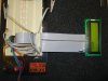
I've got a DEM16216 16x2 LCD module (https://www.electro-tech-online.com/custompdfs/2008/01/DEM16216SYH-LY.pdf) and I got it up and running and I can write characters to it.
The problem is about the contrast - I think.
The LCD contrast input V0 is connected through a 330R to the wiper of a 10k pot. The V0 is bypassed with 100nF and the supply is bypassed with 10µF close to the module. The contrast is adjusted to max readability.
The problem is after the LCD has been initialized, it sometimes, not everytime it is powered, but sometimes (approx. half the times) writes my characters in the display, and then everything disappears from the display after a few seconds.
The other half of the times, the characters don't disappear.
This is what happens when the display fails:
1. Power is applied.
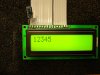
2. LCD is initialized and characters is written to it.
3. LCD displays the characters, but the characters are a bit dim.
4. 2 seconds later, the characters disappears.
This is what happens when the display is working:
1. Power is applied.
2. LCD is initialized and characters is written to it.
3. LCD displays the characters, but the characters are a bit dim.
4. 2 seconds later, the characters become clear, the dimming disappears and the characters stay on the display.
I have made a video where I connect and disconnect the power (5V) so you can see what happens. At first, the display is working, and the characters are displayed. Then I disconnect the power and reconnect it, and the display fails. Then I disconnect the power again and reconnect it, and the display fails again. Third time power is applied, the display works and shows the characters, but still with dim characters in the first 2 seconds (this is not normal LCD behavior as far as I know).
Link to video (2.5MB): **broken link removed**
Faster download here: https://www.snapdrive.net/files/318051/Forums/lcd.wmv
Any ideas?
Regards,
Futterama
I've got a DEM16216 16x2 LCD module (https://www.electro-tech-online.com/custompdfs/2008/01/DEM16216SYH-LY.pdf) and I got it up and running and I can write characters to it.
The problem is about the contrast - I think.
The LCD contrast input V0 is connected through a 330R to the wiper of a 10k pot. The V0 is bypassed with 100nF and the supply is bypassed with 10µF close to the module. The contrast is adjusted to max readability.
The problem is after the LCD has been initialized, it sometimes, not everytime it is powered, but sometimes (approx. half the times) writes my characters in the display, and then everything disappears from the display after a few seconds.
The other half of the times, the characters don't disappear.
This is what happens when the display fails:
1. Power is applied.
2. LCD is initialized and characters is written to it.
3. LCD displays the characters, but the characters are a bit dim.
4. 2 seconds later, the characters disappears.
This is what happens when the display is working:
1. Power is applied.
2. LCD is initialized and characters is written to it.
3. LCD displays the characters, but the characters are a bit dim.
4. 2 seconds later, the characters become clear, the dimming disappears and the characters stay on the display.
I have made a video where I connect and disconnect the power (5V) so you can see what happens. At first, the display is working, and the characters are displayed. Then I disconnect the power and reconnect it, and the display fails. Then I disconnect the power again and reconnect it, and the display fails again. Third time power is applied, the display works and shows the characters, but still with dim characters in the first 2 seconds (this is not normal LCD behavior as far as I know).
Link to video (2.5MB): **broken link removed**
Faster download here: https://www.snapdrive.net/files/318051/Forums/lcd.wmv
Any ideas?
Regards,
Futterama
Attachments
Last edited:
