Continue to Site

Welcome to our site!

Electro Tech is an online community (with over 170,000 members) who enjoy talking about and building electronic circuits, projects and gadgets. To participate you need to register. Registration is free. Click here to register now.

  • Welcome to our site! Electro Tech is an online community (with over 170,000 members) who enjoy talking about and building electronic circuits, projects and gadgets. To participate you need to register. Registration is free. Click here to register now.

16F887 TMR0 interrupt - not accurate?

Status
Not open for further replies.

dsc

Member
Gents,

forgive a second thread so quickly after the previous one, but I can't seem to crack this on my own. I wanted to use the TMR0 in the 16F887 to toggle an output for a very short period of time (20us), effectively creating a pulse. I thought interrupts would be perfect for this, but after an hour or so messing around with a scope and some test code, I can't seem to get the timings right. Here's the code I used for tests:

Code:
void
main(void)
{

// initiate registers here used in the main code which I've deleted for testing the TMR0 interrupts

	TRISE0 = 0; 	// configured as output	
	ANS0 = 0;

	// internal OSC - 4Mhz
	OSCCON = 0b01100101; 

	TMR0 = 0;		//test tmr0 ints
	INTCON = 0b10100000;
	OPTION_REG = 0b00001000;

	
while(1) //Do this for loop forever!
{

}	// end of global loop


}	// end of main()

void interrupt ISR()
{

if (T0IF)
{
T0IF = 0;		//clear flag
RE0 = !RE0;	//toggle the output
TMR0 = 0;		//reset timer

}

if (INTF)
{
//this code is for RB0 interrupts which I've disabled for testing the TMR0 interrupts

}

}

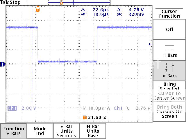
All the above does is wait for an interrupt from the TMR0 and change the state of pin RE0. Now here's a screenshot from the scope, connected to RE0:

**broken link removed**

As you can see it shows 283us between changes on RE0. Loading the timer with 0 and assigning to WDT means prescale of 1:1, so I would expect a change of state on RE0 every 255-256us, not 283us. That is a 27us error, rather big considering that I want a 20us pulse.

I've also popped the code into MPLAB Sim and timed it using a breakpoint and stopwatch. Again, identical result, 283us.

I'm surprised as I've got a PWM output, which I've checked with a scope and it's bang on precise, here's what I use:

Code:
	PR2 = 38;					//this means PWM period of 624us
	CCP1CON = 0b00001100;
	CCPR1L = 0b00000010;		//set to 2, so pulse width is 2 x 16 = 32 with 16 prescaler
	T2CON = 0b00000110;		// Prescaler set to 16 on startup, TMR2 ON, Postscaler 1:1

Looking at the scope and what's produced by the PIC on RC2, I get a period of 623.6us and a pulse width of exactly 32us:

**broken link removed**

Does anyone know where the errors might be coming from? the code is stripped to bare minimum, but I still get the dreaded 20 odd us errors on whatever value I preload TMR0 with.

Regards,
T.
 
The problem is that you are clearing TMR0 in the interrupt. :)

Remove the line
TMR0 = 0;
from the interrupt, and it will then toggle the output pin EXACTLY every 256uS (when the TMR0 int occurs).

The way you did it (writing to the TMR0 register) causes two problems;
1. the interrupt service code time is added on (ie context saving during interrupt - see PIC datasheet re interrupts)
2. AND any writing to TMR0 causes a 2 instruction delay added on (see datasheet section re TMR0).
 
Hi again RB and again thanks for your help. I've removed the line and used the following to modify the time after which the interrupt is triggered:

TMR0 = TMR0 + 56

I've put a breakpoint just above this instruction to see how long it takes this time and it's 205us, instead of 200us like I thought it would (256us - 56us = 200us). I'm guessing that's because the instruction to add 56 to the TMR takes 5 cycles (here I miss doing pure ASM, as you always know how many instructions things take)?

Looking at the timings and the value in TMR0 before the output is toggled, I can see 24 in TMR0 before it gets modified. I thought then that the minimum pulse width I can do is 24us, so I've done some tests with various values added to TMR0:


TMR0 = TMR0 + 61; toggle every 200us
TMR0 = TMR0 + 161; toggle every 100us
TMR0 = TMR0 + 211; toggle every 50us

With 211 added and a breakpoint at the end of the ISR, I can see that the ISR is finished with 237 in TMR0, so still 256 - 237 = 19 instructions which can be processed in the main loop before the ISR starts calling itself from within (ie. TMR0 reaches 256 within the ISR). Here's where things get strange, I've tried the following:

TMR0 = TMR0 + 221;

thinking I will get a toggle every 40us, but it happens every 43us instead. On first run the ISR ends with 247 in TMR0 and 24 in TMR0 before TMR0 gets modified, on the second run it finishes with 250 in TMR0 and 27 in TMR0 before it gets modified. I'm guessing something takes too much time and TMR0 overflows keeping the ISR running in a loop. I was under the impression that as long as the ISR ends with less than 256 in TMR0 it should return to the main loop and get triggered again when TMR0 gets to 256.

Any advice is greatly appreciated.

Regards,
T.
 
Using interrupts for this is not good at all (as you have seen). You should set up the timer as a PWM generator.

EDIT: Apparently you can't do PWM with timer0.. You would need to use timer1 or 2 for that. If you are forced to use timer0, then I don't see any better solutions for you.. other than using assembly. But the timing should be pretty accurate the way you are doing it. You just need to adjust for the ISR-call overhead. Make sure you have the compiler optimization tuned all the way up.

EDIT2: You could eliminate the ISR completely. Monitor the interrupt flag in the while(1)-loop.. when it triggers, do the things you need to do. This way you can eliminate the function call overhead. Of course the drawback is that you can not add much heavy computing to the application because it would interfere with the timing.
 
Last edited:
...
TMR0 = TMR0 + 56

If you write to TMR0 like this;
TMR0 = 100
it costs a 2 cycle delay (as i said before re the datasheet for TMR0).

If you read and modify TMR0 like your code;
TMR0 = TMR0 + 56
the delay will LONGER than 2 cycles, as there has to be a read operation included. Normally (going from mym memory) it will be a 3 cycle delay.

So to make a TMR0 interrupt with an exact repeating period of 100 ticks (assuming TMR0 prescaler is 1:1) you normally do this code;
TMR0 -= (100-3);

There's a limit to how short you can make a TMR0 int repeat period, as the int has many instructions for context saving, and your int code takes up time too.

If you just want to generate a 20uS pulse you can try doing it "on the fly" without the int, like this;
PORTB.F5 = 1;
Delay_uS(19);
PORTB.F5 = 0;

and check the timing on your 'scope. A decent compiler running the PIC at 4MHz will make a perfect 19uS period (ie 19 instructions length) then the last instruction that clears the port pin makes it 20uS total.
 
Cheers guys. To be honest the pulse generation is not something that has to be done in the ISR, I've just thought that it might be easier than doing it inline, but it turned out differently. I've had it in the main function before, as RB showed above with a __delay_us() function, I guess I will go back to it. The whole idea is to do the following:

1. rotary encoder connected to RB0 and RB1, interrupt triggered on RB0
2. on a RB0 int, the direction of rotation is detected and a value is inc'd or dec'd
3. a pulse is generated - this can be anything in width between 20-32us

Previously I thought I can enable the pulse output in the RB0 interrupt and enable TMR0 interrupt, which will disable the output 20-32us later. Now it seems that I will have to simply set a flag in the RB0 interrupt, go back to main() and do the pulse generation inline like this:

if (RB0_int_flag)
{
RE0 = 1;
__delay_us(19);
RE0 = 0;
RB0_int_flag = 0;
}

I'm already using the PWM output for continuous pulse generation and I will need a precise 0.1s sampling clock via TMR0 / TMR1, so it's probably better that I move this simple action back to main, rather than complicate things in the ISR.

Regards,
T.
 
If you need exactly 0.1s interrupts try TMR2, but since you have other interrupt routines there's no guarantee you won't be servicing the RB0/RB1 at the time.
You could change your interrupts to only the 0.1s and poll RB0/RB1 interrupt flags instead.

An 18F4620 is pretty much a drop in replacement for the 16F887, it has two interrupt priority levels (plus many other enhancements).
 
If you need exactly 0.1s interrupts try TMR2, but since you have other interrupt routines there's no guarantee you won't be servicing the RB0/RB1 at the time.

Argh! forgot about that, damn, I went with interrupts from RB0 / rotary encoder as it's the fastest way to service a rotary encoder. If I switch to polling I will most likely loose input from the encoder if someone rotates it really fast.

I'll look into the 18F4620...

Regards,
T.
 
...
Previously I thought I can enable the pulse output in the RB0 interrupt and enable TMR0 interrupt, which will disable the output 20-32us later.
...

You could also just put the 20uS pulse code IN the interrupt. It only takes 20uS, so if your TMR0 int period is 256uS (256 instructions) then the 21 instruction delay for the 20uS period can easily fit in your interrupt code.
 
Thought I'd resurrect this and ask another question. Is there another way of generating a single pulse from the PIC, rather than using a toggle on one of the outputs?

I'm trying to use a pulse to drive a stepper motor driver, but for some reason it doesn't work as it should, the stepper glitches and misses steps (single step operation via a tactile switch). It works fine with a PWM output from the PIC, but a single pulse doesn't seem to do the job. I was thinking maybe using the on-board PWM set to change only once and perform a single cycle, or would that be mad?

Regards,
T.
 
single step operation via a tactile switch
Are you using the switch to drive the stepper motor directly?
or
Are you using it on an input to the PIC?

Either way, it could be that you are getting some contact bounce, ie multiple electrical switching events from one mechanical operation of the switch.

If the PWM works reliably and does what you want, then why not use it?
Don't re-invent the wheel!

JimB
 
Hi Jim,

thanks for your input. The switch is fed into the PIC, debounced (in software) and on a change of state an output is being triggered for a set amount of time (40us). I've checked this with a scope and all is good. For some strange reason the drive or the motor seems to not like something about the signal and refuses to work, it does work on a bigger driver and motor though so I'm a bit lost as to why.

As for PWM, I'd have to generate a signal like this on a press of a button:

Pulse_DM856.png


[this is the pulse generated by pressing the switch]

I simply assumed toggling an output would be easiest as I do so with a simple set of instructions:

reset output
delay(40us)
set output

I always thought of PWM as something more suitable for constant operation and something I already use to drive a different motor for a set amount of time. If I decide to go down this route it means I'd have to dedicate two PWM outputs to control two motors.

Regards,
T.
 
I simply assumed toggling an output would be easiest as I do so with a simple set of instructions:

reset output
delay(40us)
set output
You are simply forgetting overhead... Once you factor that in.... "Jobs a good one"

Most people think this is a square wave with 50% duty

C:
while(1)
   {
   outputpin = 1;
   delayUs(40);
   outputpin = 0;
   delayUs(40);
   }

But because the overhead of the while statement changes it quite a bit..

To generate it properly use a timer...
 
I should've really put the original code from my program, rather then the simplified version:

C:
PORT_shadow = PORTC;
PORT_shadow = PORT_shadow | 0b00000010;	//set DIR
PORTC = PORT_shadow;					//send to port
__delay_us(50);							//slight delay before pulse is set
PORT_shadow = PORT_shadow | 0b00000001;	//set PUL
PORTC = PORT_shadow;					//send to port
__delay_us(32);							//wait 32us
PORT_shadow = PORT_shadow & 0b11111110;	//reset PUL
PORTC = PORT_shadow;					//send to port

With all the instructions the 32us delay actually turns to 41us as this was checked on the oscilloscope. As you can see the above changes two outputs, first the DIR and then the PUL. The DIR changes once and that's it, PUL gets set and then reset as the output works in a sink configuration.

Regards,
T.
 
Perhaps I'm behind the times on this one, but if your pulse is short, and you're doing it 'manually' in code, rather than using a hardware module to do it for you - you can use inline assembly for it. This means you know exactly how many clock ticks you're using, but there are some caveats. For one, referencing variables can be done, but each compiler treats it differently. For a very simple pulse with delay a few lines of basic assembly will get you a very accurate pulse - and will probably be shorter code than C..
 
Thanks for the reply Blueteeth, super accuracy is not a massive issue, I just need to make sure the pulse is longer than 2.5us and all the driver cares about is the edge of the signal (selectable to rising or falling). From the tests I've done it looks like I'm doing things right but the driver doesn't like something about the signal. I said above it works ok with a constant PWM signal, but if I try to stop / change direction or do single step driving the motor simple glitches and fails to follow the signals. I do think it's a driver issue rather than anything and I'm awaiting for more info from the manufacturer.

Regards,
T.
 
Status
Not open for further replies.

Latest threads

Back
Top