Continue to Site

Welcome to our site!

Electro Tech is an online community (with over 170,000 members) who enjoy talking about and building electronic circuits, projects and gadgets. To participate you need to register. Registration is free. Click here to register now.

  • Welcome to our site! Electro Tech is an online community (with over 170,000 members) who enjoy talking about and building electronic circuits, projects and gadgets. To participate you need to register. Registration is free. Click here to register now.

150w amplifier

Status
Not open for further replies.

artois

New Member
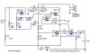
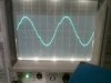
Hi all, i did this amp and i have cross over distortion as u can c in my attach, also they say to add volume control fit 10k pot inline which does not work i can only get the volume right with a 1k pot. Can u please help me set the biasing right to get rid of the distortion as i dont want to half dismantle the pcb, can i maybe use other diodes etc and what do i need to change to get the volume control right. Im building this amp for poorer folk who want something quite powerfull for outdoor entertainment just as a speaker box amp basicly. I just want it to sound descent at all volumes pls someone help. https://www.eleccircuit.com/cheap-100w-to-150w-amplifier-ocl-hifi/
Txs john
 

Attachments

  • 150w amp.jpg
    150w amp.jpg
    13.6 KB · Views: 231
  • 150w amp 10khz .jpg
    150w amp 10khz .jpg
    5.5 KB · Views: 170
If you could kindly render the circuit in a conventional way (in on left, out on right, + on top, com on bottom) and not use text-speak, you may get some help. Frankly, I am far to lazy to wrap my brains around this. E
 
Hi e
if u just click on the image and enlarge it u will see where is in, out, pos, neg, ground.
Txs john
 
It's a really, really, poor amplifier - and not capable of 150W.

A simple improvement would be to replace the two diodes (which will cause crossover distortion) with a Vbe multipler so you can adjust the bias. I agree with canadaelk, it's an apallingly badly drawn 'circuit', as well as been a very poor design as well.
 
Its schematic was saved and posted as a very fuzzy JPG file type instead of as a very clear PNG or GIF file type.

The poor TIP42 driver transistor has a max voltage rating of only 40V but its supply is 90V so it will quickly fail. It should be a TIP42C that has a max voltage rating of 100V.

The total supply is 90V so the p-p output swing will be about 84V. Then the output will be 29.7V which is only 110W into 8 ohms, not 150W.
 
not 150W.
Ah, but those are peak-to-peak pink-noise-weighted music watts, not real watts ;)
 
The output of that horrible amplifier is 150 Whats or 110 Watts.
 
Status
Not open for further replies.

Latest threads

New Articles From Microcontroller Tips

Back
Top