Continue to Site

Welcome to our site!

Electro Tech is an online community (with over 170,000 members) who enjoy talking about and building electronic circuits, projects and gadgets. To participate you need to register. Registration is free. Click here to register now.

  • Welcome to our site! Electro Tech is an online community (with over 170,000 members) who enjoy talking about and building electronic circuits, projects and gadgets. To participate you need to register. Registration is free. Click here to register now.

15 second delay with MC14541B

Status
Not open for further replies.

Burningmace

New Member
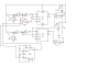
I'm developing a small intruder alarm that is triggered using a magnet and reed-switch (see this thread for the main circuit design) that needs a 15 second delay. I considered a 555, but I've read so much about them being terribly innacurate that I decided against it.

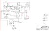
The MC14541B was suggested over at this site but I'm not sure how to set it up. From the looks of it, I could use a 4340Hz clock with a 2^16 divider (A,B set to 0,1) to bring it down to 1/15Hz. According to the datasheet, f=1/(2.3*Rtc*Ctc), but I can't work out what would be good values for the timing resistors and capacitor.

Would 47nF and 2.2k ohms be ok? My math is as follows:
1/(2.3 * 2200 * (47/1000000000)) = 4205Hz
1/(4205 / 65536) = 15.585s
Rtc = 2.2k ohms
Ctc = 47nF
Rs = 4.4k ohms

How would I link this in with my existing circuit (see other thread)?

Also, can I use a 7474 from the output pin of the MC14541B to latch the output high and drive a siren oscillator circuit? The idea would be that the output pin would go to the clock of the 7474, and the D and RST pins would go to the key switch like the ones in the original circuit do. I could then use a transistor (2N2222, BC108, etc) to switch the oscillator on and off.
 
For a 15sec delay, the effort is hardly worth it. One RC time delay is as good as another. You are quibbling about the temperature stability of one type of capacitor vs another.

The temperature stability of the resistors in the two circuits is the same. The voltage stability vs power supply voltage and temperature is much better in the 555 (truely ratiometric 1/3 and 2/3 Vdd) compared to the CMOS trip points in the other.
 
how accurate does a burglar need??

I mean .1 seconds one way or other??
have a 555 with a crystal attached which is maybe more accurate??
go with the 555 or the 7555
save lots of headaches
if worried about accuracies why not go with a PIC?
much simpler to build an alarm
 
The datasheet for the MC14541B says to use a timing resitor of 10k ohms and higher.
It is low power and does not have enough output current to drive an old-fashioned and power-hungry TTL input.
 
One of the main reasons I dislike using 555s (aside from their innacuracy) is that Multisim doesn't simulate them properly 90% of the time and I like to see results before I build things. However, I can see that with the right setup it's gonna save me a lot of time.

Could someone show me a design for a one-shot 15 second delay 555 that could link in with my existing circuitry?
 
I'm looking at this circuit:
**broken link removed**

If I swap the 1M for a 330k and the 1uF for a 47uF, will I get around 17 seconds?

Math:
1.1 * (0.000047 * 330000) = 17.06100

The issue is that when I simulate this in Multisim I get absolutely no result. Every pin on the 555 sits at a constant voltage and the output pin stays low. When using their default values the same applies.
 
Last edited:
Never mind, got the simulation working. I'm now using 470k and 47uF for my values based on this design.

The problem now is that my trigger is not a pulse, it's a constant high signal. How can I generate a single pulse from the rising edge of my trigger?
 
inserting a 555

here is a basic schematic to integrate a 555 into your circuit
still think a PIC would work better , less parts, better accuracy etc.
needs work but ???
 

Attachments

  • bulgar alarm.PNG
    bulgar alarm.PNG
    24.4 KB · Views: 504
Thanks, but could you clean it up a bit and at put arrows towards where I'm meant to connect things up? Right now I can't make out a lot of it (e.g. the bottom right 7404 doesn't seem to do anything).

I don't want to use a PIC at all in this project for three reasons:
1) Whilst I'm OK with C for PICs, I wouldn't call myself anything but a beginner. My PICASM is extremely rusty too.
2) My friend who doesn't have a PIC programmer board or an ounce of programming knowledge wants to build this too.
3) With no PIC it's easier to understand the logic from the schematic alone.
 
revised schematic

when output of U1 goes low it triggers the 555 for a 15 second pulse
after 15 seconds the output of U2 goes high clocking U4
If sw2 is not closed before 15 seconds then output of U5 pin9
goes low thus
triggering the alarm.
unused TTL inputs must go somewhere, not floating thus they
are grounded.
using the unused portions of the 74ls00 saves having to use transistors.
a 556 timer could be included to indicate if the alarm was triggered
with a blinking LED.the unused portions of the 74ls04 could also be used for the
blinking LED
this circuit needs to be checked and bread boarded before actually assembling.
it is based on your original post but does it really work??
added decoupling caps to all Vcc/ground connections of all IC's
hope this helps but haven't really deciphered entire logic table
A PIC can be had for less. numerous people on this site can program and send you a PIC. just parts and shipping + programming fee if any.
fairly simple program, two inputs, couple outputs probably less than 20 lines of code.
 

Attachments

  • burgle alarm.PNG
    burgle alarm.PNG
    29.5 KB · Views: 637
Status
Not open for further replies.

Latest threads

New Articles From Microcontroller Tips

Back
Top