Continue to Site

Welcome to our site!

Electro Tech is an online community (with over 170,000 members) who enjoy talking about and building electronic circuits, projects and gadgets. To participate you need to register. Registration is free. Click here to register now.

  • Welcome to our site! Electro Tech is an online community (with over 170,000 members) who enjoy talking about and building electronic circuits, projects and gadgets. To participate you need to register. Registration is free. Click here to register now.

12v to 5v

Status
Not open for further replies.

TuscanT

New Member
12v to 5v Resistors

Hi guys

Quick question.

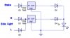
Id Just like to know what exact kind/rating of a resistor would be suitable to use in stepping down 12v to 5v which can handle around or at least 800mA (im not 100% on the mA rating as the source is from a car battery).

Also what would be a suitable diode that can working inline with the resistor?

Thanks
 
Last edited:
Hi TuscanT,

using a resistor you will have three problems.

1. The resistor has to dissipate at least 5.6W at 12V. A car battery under charge will supply 14.4V max which increases the power loss to 7.52W.

2. The desired output voltage will never be 5V stabilized. Depending on the circuit you are going to connect there is a high probability to fry it.

3. The AC spikes from the car alternator are 40Vpp (average). If they get through to your circuit unfiltered they will with 100% probability kill it.

To gain stable and smooth DC off a car battery the minimum requirements are: chokes in both, the positive and the ground line, overvoltage supression diodes, capacitors to smoothen the DC, a fixed voltage regulator (an LM7805 will be sufficient in your case) and some decoupling capacitors for the regulator to prevent oscillations and overheating. A suitable heatsink is recommended. Do not connect the heatsink to the car's ground, because this will null the effect of the choke.

Boncuk
 
I'd suggest using a voltage divider at the very least, and a voltage regulator if you at all can. Using just one resistor you'd need to have at least a 6 Watt resistor for the job and it would get hot. You'd also need to know the actual current draw to calculate the resistor value you need.

A car battery can supply much, much more than 800 mA--the current draw will be determined by the load you're driving, not the power supply. What is the rating of the device you're trying to supply?


Torben

Edit: Plus what Hans said. :)
 
Last edited:
The device i am trying to power are a cluster of Leds, they already have maximum load resistors etc built in to the unit to prevent damage and create a stable light output.

what i have is one neutral wire and two positive wires (one brake, one side light) supplying the same voltage. now what i want to do is to have the LEDs running at half power 5-6v (using positive wire 1) normally and with the brakes pressed the full 12v (using positive wire 2) there would be no need for resistors for the unit to run the full 12v
 
Use a 7805 regulator with a clip on heat sink to get 12V down to 5V. Connect positive wire 1 to its input, its 'gnd' to your neutral, and its 'out' to a 1N4002 diode (forward biased) to the LED array. Connect positive wire 2 (from the brakes) to the output side of the diode.

This way, it always feeds 5V to the LED array, until the brake is actuated. Then the second positive line goes high, goes to +12V to feed the LED and the diode protects the regulator from seeing the 12V.

This requires a 7805 regulator in a TO-220 package, a 1N4002 diode, and a clip on heatsink for the 7805. Total cost, about one to two dollars.
 
I hope the LEDs will be as bright as the light bulbs they replace.
I see many teenagers driving around with LED lights that you can hardly see. The cops catch as many as they can.

I hope your LEDs are wide-angle like the light bulbs they replace. Many cheap LEDs just tightly focus them so on-axis they are bright but to the side they cannot be seen.
 
Use a 7805 regulator with a clip on heat sink to get 12V down to 5V. Connect positive wire 1 to its input, its 'gnd' to your neutral, and its 'out' to a 1N4002 diode (forward biased) to the LED array. Connect positive wire 2 (from the brakes) to the output side of the diode.

This way, it always feeds 5V to the LED array, until the brake is actuated. Then the second positive line goes high, goes to +12V to feed the LED and the diode protects the regulator from seeing the 12V.

This requires a 7805 regulator in a TO-220 package, a 1N4002 diode, and a clip on heatsink for the 7805. Total cost, about one to two dollars.

Thanks for taking the time to write that. is there a Schematic or diagram you could show me for this. Im a little confused. Does the single neg of the led go straight to the car and the single positive of the LED split into to two. (one for the regulator and one for the diode?) and also you mentioned connect the regulators ground to the neutral. does the regulator need a separate negative to power it or something? excuse me for my lameness...im still a newbie

@ Audoguru

The LED's are extremely bright and much brighter than the original bulbs on my car. they in a OEM pre-built casing that came of another car
 
Last edited:
A 7805 is unnecessary. Just use enough series diodes to reduce the brightness on the side light circuit to make the brightness correct. I concur with audioguru; this might seem like a cool project but please don't compromise visibility (or safety).

You'll probably need an additional series diode in the 'brake' line to avoid feeding side light voltage into the brake circuit. It might make unwanted LEDs light, but it also could fool your ABS system into thinking there's an electrical problem.

Please fill in your location in your User CP.
 
There was another thread on this a few months ago. I think there was a diagram. If you can't find it I'll draw one tomorrow.

Search for 'range rover' I think.
 
Last edited:
A 7805 is unnecessary. Just use enough series diodes to reduce the brightness on the side light circuit to make the brightness correct. I concur with audioguru; this might seem like a cool project but please don't compromise visibility (or safety).

You'll probably need an additional series diode in the 'brake' line to avoid feeding side light voltage into the brake circuit. It might make unwanted LEDs light, but it also could fool your ABS system into thinking there's an electrical problem.

Please fill in your location in your User CP.

Can you suggest a suitable diode that i could use? how many to get desired effect?

As aforementioned the LEDs are OEM from another car and are wide angled and very bright almost blinding without an appropriate frosted filter

@ Mmeary

Funny you mentioned that as i think it was me that started that tread almost a year ago now the one i think your referring to. non of the suggestions worked without problems i.e heat, lights on dash board etc so im trying this time to make as simple as possible
 
Last edited:
An ordinary diode with a 3A or so rating should be good. You'll probably need 10 to 15 of them in series. Check the archives for the previous schematic.
 
would there be heat issues doing so? im assuming i would need a few diodes on both positives and the single negative source?
 
Last edited:
There will be a heat issue, but I think it is addressed by the total number of diodes. No diode is required in the negative (in most vehicles GND) line.

If there is not a schematic in the thread I referenced, let me know and I'll draw one.
 
There will be a heat issue, but I think it is addressed by the total number of diodes. No diode is required in the negative (in most vehicles GND) line.

If there is not a schematic in the thread I referenced, let me know and I'll draw one.

I did a search before and i didnt find one for what you are referring too. id appreciate if you can show me one or draw one up.
 
I posted a similar thread back in June and got some good info . My current demand was higher than 800mA.
It was /is 2.0 amps nominal. I was advised to use a "buck regulator". I'm still trying to get to grips with the practicalities of it.

Data sheets for "DC to DC" converters and "Switch mode regulators" will give you some interesting circuits for consideration.

**broken link removed**


**broken link removed**

the aboe links may be of some assistance.

J McG
 
800mA is alot of LED current. Yours must be high-brightness LEDs used in newer semi-trailers instead of incandescent lamps. A fixed regulator for the lower voltage will work fine. Dual-filament LEDs can be used, if you can find them.
 
shokjok said:
Dual-filament LEDs can be used, if you can find them.
That's a contradiction in terms - LEDs don't have fillaments.
 
Actually a contradiction in terms would be a oxymoron. His statement was just an error in statement. :)
 
Maybe it will help
 

Attachments

  • Led.jpg
    Led.jpg
    32.3 KB · Views: 385
Status
Not open for further replies.

Latest threads

New Articles From Microcontroller Tips

Back
Top