Electro Tech is an online community (with over 170,000 members) who enjoy talking about and building electronic circuits, projects and gadgets. To participate you need to register. Registration is free. Click here to register now.
Welcome to our site! Electro Tech is an online community (with over 170,000 members) who enjoy talking about and building electronic circuits, projects and gadgets. To participate you need to register. Registration is free. Click here to register now.
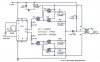
It appears to be a simple square-wave inverter with each half of the split-input winding alternately connected the the +12V by the darlington transistors.
The darlington transistors have a relatively high on-voltage so the efficiency would be poor.
I already explained all this in a PM about 6 hours ago.
Also 3 pins of the IC are not connected so it won't work.
It is a stupid simple circuit without any voltage regulation. Most electronic products will not work from its square-wave.
Why do websites post garbage circuits like this with so many errors?
This site uses cookies to help personalise content, tailor your experience and to keep you logged in if you register.
By continuing to use this site, you are consenting to our use of cookies.