Electro Tech is an online community (with over 170,000 members) who enjoy talking about and building electronic circuits, projects and gadgets. To participate you need to register. Registration is free. Click here to register now.
Welcome to our site! Electro Tech is an online community (with over 170,000 members) who enjoy talking about and building electronic circuits, projects and gadgets. To participate you need to register. Registration is free. Click here to register now.
Couple of questions:
How large is the filter capacitor after the bridge rectifier?
What is the VA rating of the transformer? (VAC and AC amps)
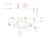
You are drawing motor current through D5, a 1N4148, which can handle 100-200ma at the most. D5 isn't necessary unless you have some other unusual circuitry connected that is not shown.
And while at it, how about showing the connections to the motor and transformer so we don't have to use our imaginations? There could be a clue there too.
There isn't a filter cap.
i have tried several transformers the smallest Va of the transformers is 12v 100ma. I would like to use my center tap transformer 6v/6v then my bridge rectifier. Output is 12.13v dc transformer is rated for 4.5 amps this circuit runs 100 ma but i will need extra power to run my lighting circuit 100ma and another 100 ma thermostat controller. I have a 300 ma transformer as well.
The funny thing is that my led lighting works on ac or dc, my thermo wants ac not dc and my motor control wants dc not ac. There picky little circuits.
And while at it, how about showing the connections to the motor and transformer so we don't have to use our imaginations? There could be a clue there too.
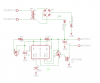
the 12vinput-1 &-2 are the 120inputs the secondary output is 6v/6v. As for the motor they just connect to the motor from the motor connectors on the schematic. And another fix is the 6k8 resistor is actually a 6m8. Typo
actually here is the circuit fixed up sorry i got in a hurry. The only reason that the 1n4148's are in the circuit is that the design originally had a onboard transformer. I took it off but left the diodes.
Are D1 and D2 around the correct way? Is the bridge around the correct way. What is 6M8? 47u is far too high, Pin 1 goes no-where. No values for R8 and R9. The chip is labelled IC2. 1N4148 diodes should not be used for 100mA. How many mistakes can a person produce on a such a simple circuit? You must take the prize. If the motor takes only 100mA, why use a FET?
Well you need one. Especially if it is like the circuit in post #7. Try 1000uF or so for C7. As collin55 pointed out, there are multiple mistakes in the circuit. You need to redraw it.
Are D1 and D2 around the correct way? Is the bridge around the correct way. What is 6M8? 47u is far too high, Pin 1 goes no-where. No values for R8 and R9. The chip is labelled IC2. 1N4148 diodes should not be used for 100mA. How many mistakes can a person produce on a such a simple circuit? You must take the prize. If the motor takes only 100mA, why use a FET?
This circuit was designed for me. it was designed for 12v i am trying to run it off of a transformer. 6M8 is a 6.8M resistor. Pin 1 is a grd and is not required by eagle to connect the program connects it for me. There is more to this circuit. thats why the labels are that way. This is a isolated circuit from the rest. i could take out the n14148's they were there when i had the circuit designed with and onboard transformer. The mosfet is in place in order to allow for upgrades. Plus i have about tem of these fets to use up.
So anyhow, If want to help please feel free if you just want to criticize I'm sure you can find spelling and grammatical errors as well, You could also search my user name and poke fun at my other posts as well. I mean what else is there to do on a Friday night for people like ourselves, except i've got kids to watch, How about you?
Well you need one. Especially if it is like the circuit in post #7. Try 1000uF or so for C7. As collin55 pointed out, there are multiple mistakes in the circuit. You need to redraw it.
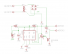
The P-channel Mosfet is a follower. When its gate goes to ground then its source will be at about +10V, not 0V. Then the motor gets only 2V.
Use an N-channel Mosfet with its drain driving the motor wire to 0V.
ok, I swapped the cap from a 4.7uf to a 1000uf. Didn't make a differants, i also added a voltage regulator. all it did was drop the voltage down to 11.64vdc when it was reading 12.13vdc. So what else could i try?
Actually, i got it working with the mosfet and the 4.7uf. I just turned the circuit on left it for a while when i came back it's working. I assume that ithe circuit needed time to charge the caps. I don't really know why it works but it does now. So thanks for ya'll input.
What kind of "NE555" are you using? 6.8M is an awfully high resistance to be putting into the RC circuit. Some types of "555" take more than 1 microamp on the trigger/threshold pins and 6.8M can barely supply this. I would change R11 to no higher than 2.2M and adjust R9, 10, and C6 accordingly.
This site uses cookies to help personalise content, tailor your experience and to keep you logged in if you register.
By continuing to use this site, you are consenting to our use of cookies.