Continue to Site

Welcome to our site!

Electro Tech is an online community (with over 170,000 members) who enjoy talking about and building electronic circuits, projects and gadgets. To participate you need to register. Registration is free. Click here to register now.

  • Welcome to our site! Electro Tech is an online community (with over 170,000 members) who enjoy talking about and building electronic circuits, projects and gadgets. To participate you need to register. Registration is free. Click here to register now.

120 Volt LED indicator lamps

Status
Not open for further replies.

RODALCO

Well-Known Member
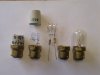
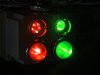
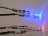
Attached are a few photo's from home made LED indicator lamps for control panels.
These are used in substations and fed from a 120 Volts DC supply.

I have built and tested various types of these LED lamps and we have had no faillures yet over the last year.

Normally 130 Volts, 15 Watt incandescent lamps are fitted but they don't seem to last ( ± 2 months ), especially when the circuitbrakers operate frequently.

The series resisitors used are 5k6 or 6k8 , 1 Watt.
a 1N914 blocking diode is used in case of reversed polarity.

Red Leds are 5000 mCAD Ø 5 mm.
Green Leds are 10000mCAD Ø 5 mm.

Regards, Raymond
 

Attachments

  • DSC03304.JPG
    DSC03304.JPG
    102.5 KB · Views: 1,327
  • DSC03297.JPG
    DSC03297.JPG
    123.5 KB · Views: 856
Led bulb.

Hi Raymond,

By bypassing the leds with a diode you loose half of the applied
power, but if you would use it you could reduce the dissipation
in both resistors to 50 %. :eek:
Maybe you could squeeze in a little capacitor too.

on1aag.
 

Attachments

  • Led bulb.GIF
    Led bulb.GIF
    8.5 KB · Views: 729
You have missed the fact that this is a DC supply, the diodes are only there to protect against reverse polarity.

I take it you're using two 5k6 resistor in series to get 11k2.
 
Hi Hero999,

Hero999 said:
You have missed the fact that this is a DC supply, the diodes are only there to protect against reverse polarity.

I usually read the posts diagonally, I guess I've must have taken the
wrong diagonal. :eek:
Anyway it's protected against reverse polarity. :D

on1aag.
 
Just another point, I know it's stating the obvious but you need to make sure that the bulb is put in so the polarity is correct or else it won't work.
 
Thanks for your replies guys.

The application i use this set up is for DC indicator lamps in 11 kV substations, which run on 120 Volts dc from a battery bank.

Hero999 I use two resistors in series to dissipate the power over two instead of one resistor, which are easily available at electronics shops.
Most high efficiency leds are already very bright at 5 to 10 mA anyway. so there is no need to run the leds at 20 mA.

And of course you have to ensure that the polarity is correct at the other lamp terminal, which happened to be off. Most POCO's wouldn't be happy to trip feeder brakers to check a status indicator light. A small bridge rectifier could be inserted in the DC application, but i like to keep it as simple as possible.

On1aag The same concept can be used for AC as well. As already suggested use a 1N4007 diode in series with the circuit to reduce the power dissipation in the series R's.
Or the other concept can be used with the bridge rectifier too. The led will than run at 100 Hz.

Regards, Raymond
 
For 230 Volts application i use 2 x 33 k :eek:hm:, 1 watt resistors in series and a 1N4007 diode. ( 2 x 27, 39, 47 k:eek:hm: )

I posted that a while ago regarding the 230 volts pilot lights, but here is the photo attached to keep all led indicator lamps together.
I like to run these at lower currents to keep the dissipation in the R's low.

Of course two or more leds can also be run antiparrallel on AC.

Regards, Raymond
 

Attachments

  • DSC01066 230 Volts Leds.JPG
    DSC01066 230 Volts Leds.JPG
    114.8 KB · Views: 709
About 2 years ago kids about 12 years old wore big belt buckles with a scrolling display. They were made in China and worked well.
I didn't see any this year.
 
1N914/1N4148 (Fairchild) are only rated at 100V, so they don't really protect a 120VDC circuit from reversed polarity. iirc, some suppliers rate these diodes at a lower voltage.
 
There are more and more commercially available LED replacements for small incandescent lamps, of many different voltage and base types. I recall finding a replacement for a 120vac 7 watt screw based lamp in a large industrial variable speed drive system.

We only got about several months continuous life even with 130vac rated incandescent bulbs, but the LEDs have paid for themselves many times over even at a $15 each cost (labor you know). Plus it keeps the operators from busting the bulbs trying to unscrew them from their sockets ;)

Lefty
 
mneary

Those 1N914 or eq. diodes are fine.
The resisitors drop the voltage to a forward voltage of about 5 x 1.7 = 8.5 volts for red leds, so that is the maximum reversed voltage they are subjected too.
In forward mode they drop about 0.7 volts so they are certainly adequately rated.

Leftyretro

That was also a problem that we had that the incandescent bulbs sometimes came apart in the socket during replacement or were very hard to remove.

For me this is an easy overtime job to assemble these LED lamps at home and install during routine inspections at POCO substations.
 
Last edited:
@RODALCO
yes i do remember.i think you posted that circuit around 1 year back.
and it worked like charm for me.my supply is 220v so i followed ur design.imean with the IN diode and the resistors.i used only one LED for table decoration purpose.and from past 1 year it never stopped working.

now i want to go further.i want to replace some low watt bulbs with the LED lighting.i bought some LED lamps from market,there were 5 LED's.and the circuit uses some diodes,2 caps,and some resistors.the big problem is the circuit generated so much heat.that it melted the bulbs top portion along with the LEDs.
so what changes are necessary to make the circuit(RODALCO's 230v circuit) to handle some 10-20 LED's and 5 leds for low watt applications.
 
RODALCO said:
Those 1N914 or eq. diodes are fine.
The resisitors drop the voltage to a forward voltage of about 5 x 1.7 = 8.5 volts for red leds, so that is the maximum reversed voltage they are subjected too.
In forward mode they drop about 0.7 volts so they are certainly adequately rated.

Wrong assumption. There is virtually no current flow and thus no voltage drop across the series resistors before breakdown occurs. Full 120V is across the LED+diode combination.

Use a 1N4007 instead.
 
Doubt it, I have not had one of those 1N914 diodes fail in nearly 17 years on metering led potential circuits.

The resistors take care of the voltage drop.
 
fever

Basically put 2 strings of 10 LED's in anti parrallel. for a 20 LED lamp.

For white LED's that is about 30 Volts drop, You need to get rid of ( 220-30 ) = 190 Volts in the series resistors. Run these at 5.75 mA than a 33 k ohm resistor would suffice. From U=I*R 190 / 33000 = 5.75 mA.
Power rating P=I²R then 0.00575² * 33000 = 1.1 Watts dissipated in the series R's.

I would go for 2 * 15 or 18 k. ohm 1 or 2 Watt series resistors to spread the heat a little.

For your 5 Led lamp I would put 2 Led's in forward mode and 3 Leds in reverse. Then use a 39 k ohm series resistor. or make it up from 2 * 22 k Ohms.

It is good practise to check the actual LED current in your circuit with your multi meter.

I find that most high efficiency LED's give excellent brightness at 5 to 8 mA's.
and i only have used 3000 to 5000 MCAD Led's.
 
RODALCO said:
Doubt it, I have not had one of those 1N914 diodes fail in nearly 17 years on metering led potential circuits.

The resistors take care of the voltage drop.

More to the point, the LED's mean there's only a small voltage across the diodes - the resistors simply limit the current.

No problem using those diodes!.
 
RODALCO said:
The series resisitors used are 5k6 or 6k8 , 1 Watt.
a 1N914 blocking diode is used in case of reversed polarity.

A blocking diode is put in series to block off the voltage. This need to be rated higher than the applied voltage.

A by-passing diode, which is connected in anti-parallel with the LED, would reduce the reversed voltage across the LED because of its forward voltage drop of 0.6V.

I was referring to the first case.
 
@RODALCO

i made a simple circuit diagram.pls have a look and let me know abt the mistakes.
**broken link removed**

and for application i will run this setup for 12 to 15 Hrs.so is it safe.
 
Status
Not open for further replies.

Latest threads

New Articles From Microcontroller Tips

Back
Top