Continue to Site

Welcome to our site!

Electro Tech is an online community (with over 170,000 members) who enjoy talking about and building electronic circuits, projects and gadgets. To participate you need to register. Registration is free. Click here to register now.

  • Welcome to our site! Electro Tech is an online community (with over 170,000 members) who enjoy talking about and building electronic circuits, projects and gadgets. To participate you need to register. Registration is free. Click here to register now.

12 volt regulator circuit

Status
Not open for further replies.
Sorry but that's total nonsense.

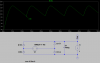
Let's simulate this example on LTSPICE.

A 12V transformer is modled as a 50Hz sinewave with peak voltage of 17V.

The linear regulator is modeled as a 1A constant current load, which is what it essentially is.

The ripple vally is 8.9V which is no good for an LM7808, let alone an LM7812.

Increasing the capacitor to 10,000:mu:F increases the ripple vally to 14.5V which is just about alright but I'd go even higher, I'd add another >3300:mu:F in parallel as the capacitor might only be 8000:mu:F. Always assume that the capacitor will be at the lower end of its tollerance when calculating ripple.
 

Attachments

  • SPICEsim rect 12V 1000uF 1A.PNG
    SPICEsim rect 12V 1000uF 1A.PNG
    32.3 KB · Views: 216
  • Rectifier.asc
    1.2 KB · Views: 154
Last edited:
Hero,

You are confusing what is economical with what is possible. I never said it was impossible to get rid of the ripple with the capacitor, I implied that it was not the way things were typically done.

It is less expensive to use a $4 transformer, $0.30 cap and a $0.15 regulator than it does to use a $3 transformer, $2 cap and a $0.15 regulator.

The normal designs only use the cap to keep the supply going when the instantaneous line voltage is below the RMS value or thereabouts.
 
Hero,

You are confusing what is economical with what is possible. I never said it was impossible to get rid of the ripple with the capacitor, I implied that it was not the way things were typically done.
Obviously a capacitor on its own will never completely eliminate ripple totally, it just needs limiting to an acceptable level and all I'm saying is that 1000:mu:F/1A won't always do this.


It is less expensive to use a $4 transformer, $0.30 cap and a $0.15 regulator than it does to use a $3 transformer, $2 cap and a $0.15 regulator.
Well if you want to design cheap and nasty junk that doesn't work properly then fine, use your 1000:mu:F/A rule of thumb.

Normal designs only use the cap to keep the supply going when the instantaneous line voltage is below the RMS value or thereabouts.
Well in the example above 1000:mu:F/A didn't even do that, it droped down to 8.9V, way below the RMS value of 12V.

I'd rather keep the instantanious voltage above the absolute minimum voltage required for the design to operate properly. In the case of a linear regulator, this means keeping it above the dropout voltage plus the output voltage.

To be picky we really need a higher voltage transformer, because if the mains voltage is on the low side then it will probably dropout slightly.

In practise, different loads have different ripple requirements. A motor (as we discussed on Electronics Lab) won't need a capacitor at all but a linear regulator and audio amplifier will.
 
It=CV
12V transformer x 1.414 = 17VPK
17V - 15V needed to keep a junk 12V regulator alive = 3V
8mS for half a 60Hz cycle say 5mS you actually need to hold up for
C=5000uS/3V=1670uF
so it should really be 2000uF/A not the 8-10KuF you were suggesting.
 
Last edited:
Rules of thumb are fine when the work most of the time, in this case the one Ubergeek63 gave doesn't, falls short of meeting the requirements by a very wide margin.

Ubergeek63 said:
It=CV
12V transformer x 1.414 = 17VPK
17V - 15V needed to keep a junk 12V regulator alive = 3V
8mS for half a 60Hz cycle say 5mS you actually need to hold up for
C=5000uS/3V=1670uF
so it should really be 2000uF/A not the 8-10KuF you were suggesting.

SPICE says otherwise, perhaps you should try it for yourself.

You also forgot the 1.4V drop for the bridge rectifier and made a mistake with your arithmetic, 17 - 15 = 2, not 3.
 
Last edited:
You also forgot the 1.4V drop for the bridge rectifier and made a mistake with your arithmetic, 17 - 15 = 2, not 3.
While you are correct in that I forgot about the diode drops, which BTW tend to be 1V or more at rated current, Bob Pease has often answered people not to rely heavily on simulations since they are often flawed by poor models.

I am only pointing this out, since you are fond of them, not implying that it is wrong in this particular case. If, for instance, you used a generic diode model you would definitely get the generic 0.6V drop instead of the more likely 1-1.2V of a fully loaded rectifier.
 
The generic model used in the simulation can't be that bad, on closer inspection of the graph it has a voltage drop of 1.7V (0.85V per diode) at the current drawn.

I agree SPICE isn't perfect, there are also other things that the simulation probably missed, like the ESR of the capacitor and that the transormer will have a much higher voltage than 17V off-load and will drop down when loaded. These things can be added to the model but there are other things like: dielectric absorbtion and changes occuring as the temperature of the components rises (due to self-heating) are harder if not impossible to simulate.
 
indeed. the graph is based on low duty cycle so they can get the 25C drop. I do not recall any statement of actual diode type, and the model certainly does not include the simple difference of the amount of copper on a PCB.

Real high end software actually does pretty well at that, but it has everything including actual copper dimensions at it's disposal. It even has airflow input options as well as heat sink aluminum models.

On reflection, most of the transformers are a bit higher for just that reason, 6.3VAC for 5VDC for instance.
 
A 6.3V transformer isn't really a high enough voltage for a 5V regulator.

8*1.414 - 1.4 - 2.5 = 4.8V.

I'd use a 9V transformer.
 
true enough, marginal at best. I would have to assume at that point that the ones that use that combination are not using junk regulators.
 
I didn't even include the ripple headroom so even with an infinite filter capacitor it'll dropout.

If I were to build a 5V regulator with a 6.3VAC transformer I would use a low dropout regulator like the LM2940CT5.0 and a huge 10,000:mu:F capacitor.
 
Status
Not open for further replies.

New Articles From Microcontroller Tips

Back
Top