Continue to Site

Welcome to our site!

Electro Tech is an online community (with over 170,000 members) who enjoy talking about and building electronic circuits, projects and gadgets. To participate you need to register. Registration is free. Click here to register now.

  • Welcome to our site! Electro Tech is an online community (with over 170,000 members) who enjoy talking about and building electronic circuits, projects and gadgets. To participate you need to register. Registration is free. Click here to register now.

12 volt regulator circuit

Status
Not open for further replies.

mmuste01

New Member
:confused: Hi,

I have a transformer with 20 VAC on the secondary. I run that through a bridge rectifier and come out with 17 volts. If i connect a 220 micro farad cap on that output to ground then the voltage on the cap + keeps climbing to 35 volts. How or why does that happen??

I took the cap out and i get 15 vdc out of the 7812 instead of 12. Can anybody enlighten me?

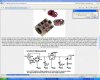
It's the ckt on the attached jpg.

Please help!

Thanks!
 

Attachments

  • clip_image002.jpg
    clip_image002.jpg
    56.1 KB · Views: 803
you want either a 10 or 12V transformer. 20V is blowing out the 7812. depending on the specific one they vary from 25-50V max input.

nominally the 20V RMS will charge a capacitor to it's 28V peak. once you make allowance for the line voltage tolerance of 20% you blow the 7812. That is under normal conditions, there can also be noise and surges on top of that.
 
Last edited:
:confused: uuuuh

Hang with me here. Don't leave me now!

How does the 7812 get blown with 20 volts in if it will tale 25 to 50?

How could a 10 or 12 volt txformer make the 7812 put out 12 volts. Doesn't the input have to be more than 12?
 
20V is the DC equivalent of the AC voltage. the capacitor charges to the peak voltage which is 1.414 times the AC voltage giving you 28V.

20VAC is the full load transformer rating. there is a characteristic called regulation. for small transformers it is typically 20%. therefore if you do not have any load attached your transformer output will be 20% higher.

20V RMS * 1.141 * 1.2 = 35V on the capacitor under no load conditions.

20-50V rating is the absolute max the chip will handle. it is not a range for a single chip, it is a range across manufacturers chip variations.
 
I went and got a 12 volt transformer and now i finally have 12 volts on the output of the 7812. But, when I connect the load which is an LED light strip which draws 132 ma, the voltage goes down to 11.4 and the current drops to 117 which is not high enough. How can I keep the 12 volts from falling?

Thanks
 
That's nothing, there's too much ripple, you need a much larger capacitor than that.

Use a 2200:mu:F capacitor minimum.
 
Last edited:
Thanks guys. It's working now. I put a 2200 uf cap in but it still didn't work because my transformer was too small. got a new one and it works fine. Learn something new every day!
 
Surely doesn't that depend on the ripple you desire?

I always go by the following formula:

[latex] C = \frac{I}{2FV}[/latex]
Where:
V = Maximum allowable ripple voltage.
I = DC Current drawn.
F = The mains frequency.

In practise the ripple voltage will be less than the figure plugged into the formula because it doesn't account of how long the current is being drawn from the supply. For a more procise estimate, I use SPICE.
 
Last edited:
of course, that is the definition of "rule of thumb"

you do not really need spice if you figure from the peak voltage and your load to get to the ripple.

one thing that I really fault the educational system for is excessive derivations. the old give a man a fish or teach a man to fish thing. The basic need to be taught and used, not "derived" out of existence. In this case it would be the charge (Q) equations:

Q=IT and Q=CV

for switchers we should add the basic inductor relationship:

dI=dT*V/L

From here we get how much the inductor current will drop when supplying a load and how long the capacitor can supply the load. between them most switcher components can be selected with reasonable success.

you do not need all the fancy formulas if you remember these simple things. if you know the frequency you can select the capacitor that will hold up the load through the switching cycle. in the case of higher power systems you might need to get a bigger capacitor to handle the ripple current but the minimum value would be known.
 
But 1000:mu:f/A isn't anywhere near high enough, did you mean 10,000:mu:F/A which would make more sense?
 
Status
Not open for further replies.

Latest threads

New Articles From Microcontroller Tips

Back
Top