Continue to Site

Welcome to our site!

Electro Tech is an online community (with over 170,000 members) who enjoy talking about and building electronic circuits, projects and gadgets. To participate you need to register. Registration is free. Click here to register now.

  • Welcome to our site! Electro Tech is an online community (with over 170,000 members) who enjoy talking about and building electronic circuits, projects and gadgets. To participate you need to register. Registration is free. Click here to register now.

12/24V square wave oscillator from 100 to 2000Hz

Status
Not open for further replies.
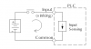
Does not a PLC input utililize a opto-isolated inputs, like this:

plc3.png
???

If so, then the "PNP driver" (shown above) only needs to source current (not sink it). Martino want to drive 5 such inputs simultaneously.

The PLC specs that I have looked at specify that the "24Vdc supply" (shown above) can vary from 12Vdc on up to a nominal 24Vdc.

My take on what Martino needs:

1. A lab DC supply that is adjustable from 12V to 24V. Alternatively, start from the DC supply that powers the PLC and add an adjustable regulator (like a LM317) to make the input voltage variable .

2. A 555 oscillator that works on any voltage from the adjustable 12V t0 24V input. Since a 555 should not be operated at voltages exceeding 18V, then it needs its own (neg) regulator.

3. A High-side driver capable of sourcing current.

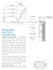
Here is my circuit useful for driving common-cathode inputs: Starting from an adjustable lab supply, a '7908 neg regulator limits the 555 voltage. The 555 output is referenced to V(cc) and drives the gate of a high-side PFET driver with a -8V square wave.

390.png


V(plc) is shown for 5 different settings of the Lab supply, from 12V to 24V
 

Attachments

  • PLC0.png
    PLC0.png
    7 KB · Views: 277
  • plc2.png
    plc2.png
    60.3 KB · Views: 292
Last edited:
NPN sink is more common with Anode to V+ at PLC
 
Tony, i will try.
Do you have adjustable 3 terminal regulators, pots, plug-in vero-board, or some means of construction?
Otherwise we may be wasting our time for this custom tester...

Which configuration are you using? Pls define Series R value. It makes a difference on transistor choice. (NPN or PNP)
**broken link removed**

Clock could be NE555 with LDO controlled voltage or Schmitt Trigger clock with pot attenuator Vout to V+ via PNP emitter follower.
 
Last edited:
Spec, MikeMl yours schematics are much appreciated,
thank you.

Tony, i am not sure to understand what are: Pls and the Terminal Board or DC Output Module shown above. A little explanation should be helpful.
 
Spec, MikeMl yours schematics are much appreciated,
thank you.

Tony, i am not sure to understand what are: Pls and the Terminal Board or DC Output Module shown above. A little explanation should be helpful.
WHat electronic construction experience do you have and test experience? It seems what we are doing may be assuming too much . To us, the PLC interface is easy to test, but since you have not given a schematic of your interface, we don't know exact polarity of interface , parts you can choose etc..

You have yet to show a schematic. Do you have this
5167413.jpg


(Pls.=Please)
 
Tony, sorry i have not such confidence with english (Pls = please : understood).
I know and use breadboard for simple circuits, no problem.
About the digital inputs of the PLC, i have not schematics; i know is a resistive input with 4mA max of load.
 
NPN sink is more common with Anode to V+ at PLC
I dispute that, but if Martino's PLC has common-anode inputs, then here is the complement of the other circuit:

390n.png
 
Last edited:
mrtino.

Can you post the spec sheet details of the PLC inputs, or a link to it's online datasheet?
 
Last edited:
According to this data sheet, the SR3B101BD requires the first circuit I posted in post#21 (PNP, common-cathode, ground-referenced inputs, high-side switch).
 
Reverse polarity protection

1 kHz for discrete input (e.g. PNP switch to 24V)

Logic "1" >= 15 V for IB...IG used as discrete input circuit
Logic "1" >= 15 V for I1...IA and IH...IR discrete input circuit

Logic "0" <= 5 V for IB...IG used as discrete input circuit
Logic "0" <= 5 V for I1...IA and IH...IR discrete input circuit <=5V

Logic "1" >= 2.2 mA for I1...IA and IH...IR discrete input circuit
Logic "1" >= 1.2 mA for IB...IG used as discrete input circuit

Logic "0" < 0.75 mA for I1...IA and IH...IR discrete input circuit
Logic "0" < 0.5 mA for IB...IG used as discrete input circuit

Thus inputs Ix for x={1 to A} and {H to R},
the unit input appears as 15V/2.2mA= 6.8 kΩ resistor to V- , (0V)
while inputs B to G uses 12.5kΩ to 0V for a load.

It would appear it was not intended for 12V operation, and unit provides 24V for use to a 3 wire interface.
+24V, 0V, Vin. Thus source impedance needs to be < 9V/2.2mA=4kΩ to guarantee pullup from 24V to 15V for Logic "1". Easy for any PNP switch, negative LDO running from 24V to make 19V difference making a 5V clock and open collector PNP output to drive input using V+,V-.

Schneider specs seem inadequate on EMI specs.

I wonder If Martino knows about EMI sources for noise, cables, ferrite, shields etc.
 
.
EMI English only, is not that useful for Martino.
 
Thank You Tony,
i much appreciate your last post about the max allowed output impedance of the oscillator.
Just a question: why you consider the 2,2mA and not the 4mA "Discrete input current" as the load input ?
EMI/EMC compliance is not an issue in my test bed.
Your EMI reference is well written, easy to understand.
 
Last edited:
martino
I was just calculating the equivalent circuit impedance of the Schneider specs based on threshold
V/I=6.8kΩ on 24V units which is referenced to V- in unit.

Any simple variable 0 to 24 Vp positive pulse generator will work that can drive 6.8k/10 =680Ω

Actually 24V/6.8kΩ=3.53mA so 4mA is just rounded up.

Do you have a variable 12 to 24V supply? If so then use Mike's circuit.
https://www.electro-tech-online.com...from-100-to-2000hz.148919/page-2#post-1273296
Use trimpot for R1 if you need to change frequency. or fixed RC changes
 
Last edited:
Good suggestion Tony,
a last question to Mike: why use -8V to supply the LM555 ?
Didn't!
the 555's Vcc pin is at any variable voltage from 12Vdc to 24Vdc. It's Gnd pin is always 8V more negative than its Vcc pin due to the negative regulator, hence it is operating on 8Vdc.

If the circuit is powered from 12Vdc, the 555 Gnd pin sets at 4V. It it is powered from 24Vdc, then the 555 Gnd pin sets at 24-8=16Vdc, so the 555 always applies either 0V source-to-gate of the PFet, or -8V source-to-gate of the PFet, depending on the state of the 555. Note that the source of the PET is tied to the variable input voltage. Most PFets will only tolerate gate-to-source voltages between 0V and -10V
 
Status
Not open for further replies.

Latest threads

Back
Top