Continue to Site

Welcome to our site!

Electro Tech is an online community (with over 170,000 members) who enjoy talking about and building electronic circuits, projects and gadgets. To participate you need to register. Registration is free. Click here to register now.

  • Welcome to our site! Electro Tech is an online community (with over 170,000 members) who enjoy talking about and building electronic circuits, projects and gadgets. To participate you need to register. Registration is free. Click here to register now.

10A current limiter circuit

Status
Not open for further replies.
I'm building a 60V 10A lab PSU and i'm almost done with all the circuits. i just need a 0 to 10A current limiting circuit. prefferably using 4 TIP3055 in parallel for the limiting. if possible, a 10 mOhm shunt would be nicer than a 100 mOhm shunt since it can be lower wattage.
i am pretty inexperienced in making my own circuits so any help would be greatly appreciated!
 
A simple approach that I use is to put the current sense resistor at the input side of the main regulator power devices, then sense the voltage across that with a differential amp.

Compare the output of that to the current limit setting using another opamp, and pull down the main reference voltage (so the PSU output voltage reduces) if the set current is exceeded.

That does not need any additional power devices.

You do need to design the voltage control section so the output voltage can drop to zero, though.
 
do you mean before the TIP3055 transistors or before the switching regulator?
OK, if it's a switching regulator it may be better to put the sense resistor in series with the negative output. Otherwise it would need some filtering which would slow the response.

That does eliminate the need for the differential amp, but it also reduces the output accuracy by the drop across that resistor, unless you add extra circuitry.
 
If you research online, you'll find current sense PSUs with the sense resistor at the negative line connected to an NPN transistor with the collector lead trickling the regulator output current when the maximum output current is approached.
 
i just need a 0 to 10A current limiting circuit. prefferably using 4 TIP3055 in parallel
If you use a linear limit circuit, those transistors will be dissipating 60V * 10A = 600W. :eek:
So you need a method to limit the output from the switch regulator directly.
Post the switching regulator you are using.
 
I'm using the LTC7810 in the dual phase one output configuration. It has two sense pins for each phase, but they arent adjustable. They limit the current when the voltage difference between them is 75mV. They limit the current by shutting off the regulator and making short voltage pulses to sense if the short circuit is gone.
The LTC7810 is actually not made to be able to change the voltage at will. I'm just using it since it's one of the only ones i found with high enough input voltage.
I am not sure about the shunt on the negative output since the PSU also has two fixed 5 and 12V outputs. I don't want the current i'm pulling from them to affect the current limiter of the main regulator.
And just in case someone asks for it: i selected 200kHz as the switching frequency.
Also the output voltage of the transformer is around 40VAC which is around 56VDC. I'm just rounding up to 60VDC since it's easier to deal with imo.
I would also like to be able to sense when the PSU is current limiting since i want to make it show up on the LCD on the front.
 
Last edited:
I'm building a 35V 10A lab PSU, i want to use 4 TIP3055 transistors for current limiting, i'm also fine with using the switching regulator to adjust the voltage so the specified current flows. I'm using an LTC3892 in the dual phase single output configuration. It would also be nice to be able to know when the circuit is current limiting so i can turn on an LED to tell me that it's limiting.
 
What current limit range do you need?
Can you add a small shunt, sense resistor (e.g. 10mΩ) between the load and ground to sense the current level?

Using the transistors for limiting will dissipate a lot of power, so better if you can limit the regulator output to control the current.
 
Last edited:
I don't see a specific question. Also, we work better when fed . . . a schematic.

ak
 
I don't see a specific question.
It seems to be implied that he wants to add a current limiter to the supply.
we work better when fed . . . a schematic.
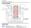
Yes, that would have been nice, but you can find the basic circuit on last page of the LTC3892 data sheet.
 
What current limit range do you need?
Can you add a small shunt, sense resistor (e.g. 10mΩ) between the load and ground to sense the current level?

Using the transistors for limiting will dissipate a lot of power, so better if you can limit the regulator output to control the current.
I would like to be able to adjust the current limit from 0A to 10A and yes, i can add a small shunt to the negative side of the PSU.
 
I don't see a specific question. Also, we work better when fed . . . a schematic.

ak
roughly what im using. Though, instead of a resistor, i connected FREQ directly to GND to select a switching frequency of 350kHz.
 

Attachments

  • Screenshot 2023-03-21 161705.png
    Screenshot 2023-03-21 161705.png
    131.5 KB · Views: 345
Is the website bugged for me or did i not create a new thread for the 35V 10A PSU? I thought i did, if i didn't, should i move this to a new thread?
 
I would like to be able to adjust the current limit from 0A to 10A and yes, i can add a small shunt to the negative side of the PSU.
I would not put the shunt resistor in the ground path.

If the load ground were to get connected to the any other ground, then the shunt resistor gets bypassed, meaning the limit circuitry doesn't know what the load current is. Since the LTC7810 is a dual output product, the probability of the two loads sharing the same ground is high.

Putting the shunt resistor in the high side does complicate the current limit circuit a bit, but I think it's worth the extra effort.
The shunt shouldn't get bridged. The VOUT connector would only connect to the regulator output and the shunt which would then go to ground. The outputs connect together for a higher current capacity
 
Last edited:
Status
Not open for further replies.

Latest threads

New Articles From Microcontroller Tips

Back
Top