Continue to Site

Welcome to our site!

Electro Tech is an online community (with over 170,000 members) who enjoy talking about and building electronic circuits, projects and gadgets. To participate you need to register. Registration is free. Click here to register now.

  • Welcome to our site! Electro Tech is an online community (with over 170,000 members) who enjoy talking about and building electronic circuits, projects and gadgets. To participate you need to register. Registration is free. Click here to register now.

100MHz frequency counter

Status
Not open for further replies.

MikeMl

Well-Known Member
Most Helpful Member
I have a 10Mhz Rubidium Frequency Standard. I'm thinking of building a 100Mhz PIC-based frequency counter using that as the time base. Should I use the 10Mhz as the PIC oscillator (assuming a 20MHz PIC)?

What is the best way of generating counting periods of 0.01, 0.1, 1, and 10 seconds? (some combination of Timer 0, 2 and software?)

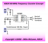
I will use an external modulo 256 high-speed counter to prescale the 100 MHz so that the highest frequency counted directly by the PIC will be 390KHz. That requires using a CCP (Timer 1) module and software to accumulate the counts?

The idea would be to gate the prescaler with the PIC derived counting period, and then be able to read the prescaler counter value into a port so that it can be concatenated with the count accumulated inside the PIC. The result would get converted to decimal and displayed on an LCD as Hz.

If a port pin is set high and then low for the duration of the counting period, will that produce a sufficiently accurate gating of the signal being counted? (different delay of the port pin going high compared to going low?) Or should I use an external high-speed toggle flip-flop so that the external gating period could be the time between two successive up-edges?

Anybody have any other suggestions.
 
Where did you get the Rubidium freq standard?? And how much? I want one. ;)

Yep I would use the 10Mhz standard as the PIC osc.

You can forget any gating system if you want accuracy. You need to use free running timers and design the period measuring software so the entry error is statistically equal to the exit error, then average over sufficient samples to cancel the errors.
 
If a port pin is set high and then low for the duration of the counting period, will that produce a sufficiently accurate gating of the signal being counted? (different delay of the port pin going high compared to going low?) Or should I use an external high-speed toggle flip-flop so that the external gating period could be the time between two successive up-edges?

Looking at the pic16f870 datasheet, rise/fall time < 40ns (< 145ns for LF part). As you are only gating a 390kHz max signal (2.56us period) the rise/fall time is insignificant. In fact, at 10MHz fosc (1/400ns), which is 6 instructions/external clock, you could afford to do all gating in software.
 
Where did you get the Rubidium freq standard?? And how much? I want one. ;)

Yep I would use the 10Mhz standard as the PIC osc.

You can forget any gating system if you want accuracy. You need to use free running timers and design the period measuring software so the entry error is statistically equal to the exit error, then average over sufficient samples to cancel the errors.

I got one of these (Datum LPRO) for $75. A fellow in the local ham club can get these from time to time.
 
I was thinking about gating the signal into the prescaler, so that I could get 8 digit precision. That means stopping the count in the prescaler, and then reading the value in the prescaler and using it to extend the count to ~24 bits. The gating accuracy would have to be about 5 ns.
That's why I'm thinking that an external toggle flip-flop which times between two successive up edges might work better.
 
Nice unit. Does it need to be calibrated like many of the Rubidium modules? I just looked at a few datasheets and most have a "freq adjust" input.

Still going with the gating idea?
 
Hi MikeMl,

Just wondering why you decided on 100-MHz?

You might consider using Timer 0 with its 1:256 prescaler for a 50-MHz counter and using a high speed divide-by-two counter on the T0CKI input to realize a 100-MHz top end.

You don't need any fancy "gate" hardware to turn the counter on and off. Just toggle the T0CKI pin from an output to an input to start the counter and after a precise period toggle it back to an output to stop the counter. Use a 1000 ohm resistor between signal source and T0CKI pin to absorb the input signal while T0CKI is configured as an output.

Timer 0 is an 8-bit counter on most PICs so you would use TMR0 register value for the middle 8 bits of your 24 bit result and use Timer 0 overflows for the upper 8 bits of the 24 bit result. With a 50-MHz input signal you could expect a Timer 0 overflow approximately every 1.3-msecs so it's important to check for overflow at least that often while counting. Capturing the 1:256 prescaler value and using it for the least significant 8-bits of the 24-bit count is pretty well documented and shown below.

Here's an example excerpt of the most significant portion of a 50-MHz counter program. I hope it gives you some new ideas.

Kind regards, Mike

Code:
NewCount
        clrf    TMR0            ; clear TMR0 and prescaler        |B0
        bcf     INTCON,T0IF     ; clear T0IF interrupt flag       |B0
        clrf    CountL          ; clear 24 bit counter registers  |B0
        clrf    CountH          ;                                 |B0
        clrf    CountU          ;                                 |B0
        movlw   200             ;                                 |B0
        movwf   msctr           ; gate timer = 200 msecs          |B0
        movlw   TRISIO          ;                                 |B0
        movwf   FSR             ; setup TRISIO indirect access    |B0
        bsf     INDF,2          ; counter "on" (T0CKI = input)    |B0
;
;  count pulses on the T0CKI input for precisely 200-msecs
;
GateOn  setz                    ; set Z = 1                       |B0
        btfsc   INTCON,T0IF     ; TMR0 overflow? no, skip, else   |B0
        incf    CountU,F        ; bump CountU, Z = 0              |B0
        skpz                    ; TMR0 overflow? no, skip, else   |B0
        bcf     INTCON,T0IF     ; clear T0IF interrupt flag       |B0
        DelayCy(1*msecs-8)      ; delay 1 msec minus 8 cycles     |B0
        decfsz  msctr,F         ; 200 msecs? yes, skip, else      |B0
        goto    GateOn          ; loop again                      |B0
        bcf     INDF,2          ; counter "off" (T0CKI = output)  |B0
        btfsc   INTCON,T0IF     ; TMR0 overflow? no, skip, else   |B0
        incf    CountU,F        ; bump CountU                     |B0
        bcf     INTCON,T0IF     ; clear T0IF interrupt flag       |B0
;
;  collect 1:256 prescaler value
;
        movf    TMR0,W          ;                                 |B0
        movwf   CountH          ; save TMR0 value                 |B0
Flush   bsf     STATUS,RP0      ; bank 1                          |B1
        bcf     OPTION_REG,T0SE ; clock on rising edge            |B1
        bsf     OPTION_REG,T0SE ; clock on falling edge           |B1
        bcf     STATUS,RP0      ; bank 0                          |B0
        decf    CountL,F        ; decrement counter LSB           |B0
        movf    TMR0,W          ;                                 |B0
        xorwf   CountH,W        ; prescaler overflow into TMR0?   |B0
        bz      Flush           ; no, clock it again              |B0
;
;  do something with the 24-bit (frequency/5) count
;
 
Last edited:
Hi MikeMl,

Just wondering why you decided on 100-MHz?

I want to go to 1GHz with a decade prescaler, so 100MHz without it. I want 1Hz resolution at 100MHz (more on this later); 10Hz resolution when using the prescaler.

You might consider using Timer 0 with its 1:256 prescaler for a 50-MHz counter and using a high speed divide-by-two counter on the T0CKI input to realize a 100-MHz top end.

The 16F873/4 I am familiar with does not have this capability. It samples the external clock with the instruction clock.

You don't need any fancy "gate" hardware to turn the counter on and off. Just toggle the T0CKI pin from an output to an input to start the counter and after a precise period toggle it back to an output to stop the counter. Use a 1000 ohm resistor between signal source and T0CKI pin to absorb the input signal while T0CKI is configured as an output.

That's clever.

Timer 0 is an 8-bit counter on most PICs so you would use TMR0 register value for the middle 8 bits of your 24 bit result and use Timer 0 overflows for the upper 8 bits of the 24 bit result. With a 50-MHz input signal you could expect a Timer 0 overflow approximately every 1.3-msecs so it's important to check for overflow at least that often while counting. Capturing the 1:256 prescaler value and using it for the least significant 8-bits of the 24-bit count is pretty well documented and shown below.

Which PICs can do this? Again, the one I most familiar with does not allow reading the value in the prescaler, and Timer 0 will not count at 50MHz.

After thinking about it some more, since I have a time base which is good to about 10^-9, I would like to have 1Hz resolution at 100MHz, which because I will be dividing by 2 to begin with, means I will have to count for 2sec. That means I will have to implement counting to at least 27 bits, i.e. 32 bit arithmetic.

To avoid a 32 bit division, is it best to generate counting intervals of 0.02, 0.2, or 2 sec?
 
The 16F873/4 I am familiar with does not have this capability. It samples the external clock with the instruction clock.

Which PICs can do this? Again, the one I most familiar with does not allow reading the value in the prescaler, and Timer 0 will not count at 50MHz.

Your 16F873 and 16F874 will count to 50-MHz. Look at parameters 41 Tt0L and 42 Tt0P in TABLE 15-4: TIMER0 AND TIMER1 EXTERNAL CLOCK REQUIREMENTS. That same table indicates that Timer 1 in asychronous counter mode is only good up to about 16-MHz.

Your 16F873 and 16F874 can read the 1:256 prescaler by toggling the T0SE edge select bit as described in my previous post.

With a 32 bit count the upper 16 bits (upper two bytes) would accumulate the Timer 0 overflows.

The 32 bit math isn't much different from 24 bit math. Mostly bit shift and add operations. The binary-to-bcd or binary-to-ascii routine is probably more involved.

Good luck on your project.

Mike, K8LH
 
You might wish to have a look at the Silicon Chip 50MHz frequency meter. It uses no external dividers and gates the signal using an IO pin. Apparently it can read up to 64MHz (this may be a limitation due to the transition time of the 74HC132 gates and not the PIC). It also uses the obsolete 'F84, so it may be possible to read an even higher frequency directly with a newer PIC model.

Circuit diagram may be seen here:
A Low-Cost 50MHz Frequency Meter
 
Last edited:
You might wish to have a look at the Silicon Chip 50MHz frequency meter. It uses no external dividers and gates the signal using an IO pin. Apparently it can read up to 64MHz (this may be a limitation due to the transition time of the 74HC132 gates and not the PIC). It also uses the obsolete 'F84, so it may be possible to read an even higher frequency directly with a newer PIC model.

Circuit diagram may be seen here:
A Low-Cost 50MHz Frequency Meter

That's a very good example and description of the old Timer 0 derived 50-MHz counter. The front-end signal conditioning looks good too. Now if they had just known how to "gate" the T0CKI input and retrieve the prescaler value all in software they could have saved two pins and replaced IC2:74HC132 with a 1000 ohm resistor.

Regards, Mike
50-mhz-counter-png.34839
 

Attachments

  • 50-MHz Counter.PNG
    50-MHz Counter.PNG
    16.7 KB · Views: 3,211
Last edited:
Just be aware of the entry error caused by using the TMR1 for external count. That's why I suggested using free running timers capturing the value and averaging over N samples.
 
I've experienced a funny first count anomaly using Timer 1 as an asynchronous counter before. Is that what you're referring to, Roman?
 
No it's to do with measuring a frequency within a period.

Let's say you can use the PIC to generate an exact 1 second period. The frequency is asynch to that period. So if you measure the / adge of the freq, the worst neg case is if the two (first and last) / edges are JUST outside the start and end of the period. So the frequency will measure as -1. The worst positive case is if the two / edges are JUST within the start and end of the period, that gives a freq error of +1;

So for that system of measurement the error of the freq you measure will be +/- 1 count.
You can live with that as the entry and exit error have the same staistical chance of occuring so after a long period of time sampling and averaging will give a zero error reading.

But the PIC TMR1 / edge count only counts the first / edge after it detects a \ edge, so you get an "entry" error at the start of the period which is not balanced at the end of the period.

You can get around it by leaving the TMR1 counter as free running (never stopping or starting it) which is closer to the solution I mentioned because at least it balances the entry and exit error. There is still an issue because you might be measuring a frequency that occurs at a beat of the period.

Going one better is to use 2 free running systems. If you manually poll the period in a PIC btfss loop it takes 3 instructions, then grab the free running TMR1 counter value, then manually poll for the end of the second and grab the TMR1 counter value. Now you have 2 sets of entry and exit errors, each set is self cancelling so combined accumulated error is zero, but the big advantage comes from the beat frequency being forced to be random (and repeating) by the manual polling loops that take 3 PIC instructions at each end of the period. It's a case where you are deliberately introducing more error of a short term cyclic nature so the accumulated average measurement will be a lot more accurate.
 
Your 16F873 and 16F874 will count to 50-MHz. Look at parameters 41 Tt0L and 42 Tt0P in TABLE 15-4: TIMER0 AND TIMER1 EXTERNAL CLOCK REQUIREMENTS. That same table indicates that Timer 1 in asychronous counter mode is only good up to about 16-MHz.

Your 16F873 and 16F874 can read the 1:256 prescaler by toggling the T0SE edge select bit as described in my previous post.
...

Ok, the light bulb finally went ON. I now see the trick of clocking the prescaler until it increments TMR0 to determine where it stopped after the TOCKI input was gated off.
 
Your 16F873 and 16F874 will count to 50-MHz. Look at parameters 41 Tt0L and 42 Tt0P in TABLE 15-4: TIMER0 AND TIMER1 EXTERNAL CLOCK REQUIREMENTS. That same table indicates that Timer 1 in asychronous counter mode is only good up to about 16-MHz.

Your 16F873 and 16F874 can read the 1:256 prescaler by toggling the T0SE edge select bit as described in my previous post.
...

Ok, the light bulb finally went ON. I now see the trick of clocking the prescaler until it increments TMR0 to determine where it stopped after the TOCKI input was gated off. Presumably, this is also the method by which the prescaler starts the next count cycle from zero?
 
Hi. The trick of extracting prescaler value by toggling T0SE bit til TMR0 increases seems very interesting, but it doesen't work for me. I'm testing it in Proteus VSM simulator wit a pic16f630. Do you know if it works on real-life pics. Thanks.
 
Perhaps a Proteus VSM problem? It works in "real-life" PICs just fine. I've used it so far in frequency counters using the 12F683, 16F628A, and 16F88.

Have fun Gentlemen.

Regards, Mike
 
Last edited:
It doesen't work neither with MPLAB SIM (I can only test on simulators at the moment), but it works perfectly toggling T0CS instead of T0SE. Thank you very much for the inspiration.

P.S.
I hope you can understand my english.

Bye

Pierluigi
 
The problem with toggling the T0CS bit as that the prescaler may start clocking the system clock during the short time that the system clock is selected as the source. I wonder if you're missing something as simple as making sure the T0CKI pin is set as an output before you start toggling T0SE?
 
Last edited:
Status
Not open for further replies.

Latest threads

New Articles From Microcontroller Tips

Back
Top