Continue to Site

Welcome to our site!

Electro Tech is an online community (with over 170,000 members) who enjoy talking about and building electronic circuits, projects and gadgets. To participate you need to register. Registration is free. Click here to register now.

  • Welcome to our site! Electro Tech is an online community (with over 170,000 members) who enjoy talking about and building electronic circuits, projects and gadgets. To participate you need to register. Registration is free. Click here to register now.

10/1 Stable? Voltage divider for 100v

Status
Not open for further replies.

JohnWondersWhy

New Member
Hello,

I have a 100 (variable) volt input that I need to drop to 10v.


So, I've used a 2700 + 300 ohm resistors (3 watt) in series to do this. The problem is that the 2700 resistor will be much warmer than the 300 causing my 10/1 ratio to vary. The ratio doesn't have to be exact; but, I'd like the system to be stable (better that 1%).

Any ideas on how to stablize the divider? Or is there an easier way (less heat) way to do this?

I'm considering potting the two resistors or probably just using a TO-220 package and piggyback the resistors together. Both in an attempt to keep them at somewhat the same temperature.


More background . . .

-the high voltage is being pulsed at 10khz
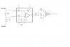
-I'm using low value resistors for noise immunity (they are feeding an op-amp and then on to a ADC)
 
If you ratio is changing with temperature, perhaps you should use some better quality resistors?.

For that matter, as it's feeding an opamp, increase the values a LOT to reduce dissipation in them - the current ones seem MUCH too low.
 
Anwsering the responses above . . .

Duty cycle ~ 10 to 60%

I initially used larger resistances; but, found that lower resistances greatly stablized the values being reported the ADC. Errors dropped from about 5% to .07%

The noise was from two sources; the always-annoying-60hz and 80khz from connected equipment.

I'm feeding the divided voltage into a differential amp (ina117) then onto a 1khz lowpass filter (opa027) then onto a ADC.
 
JohnWondersWhy said:
Anwsering the responses above . . .

Duty cycle ~ 10 to 60%

I initially used larger resistances; but, found that lower resistances greatly stablized the values being reported the ADC. Errors dropped from about 5% to .07%

The noise was from two sources; the always-annoying-60hz and 80khz from connected equipment.

I'm feeding the divided voltage into a differential amp (ina117) then onto a 1khz lowpass filter (opa027) then onto a ADC.
How are you feeding it into the ina117? Maybe you can take advantage of the diff input to get some noise rejection, if you can figure out how to make it common mode.
 
I think I'm doing what you've suggested ? (I'm by no means an expert at this) A schematic is attached.

The Hi/Lo voltage "ground" is not tied to the amplifier grounds.
 

Attachments

  • sch.JPG
    sch.JPG
    38 KB · Views: 187
JohnWondersWhy said:
I think I'm doing what you've suggested ? (I'm by no means an expert at this) A schematic is attached.

The Hi/Lo voltage "ground" is not tied to the amplifier grounds.
So how is it related to amplifier ground? Is there any connection between them? Resistive or otherwise?
 
Last edited:
Your diagram doesn't make must sense?, it appears to be missing any ground connection, and has two obscure connections to something we know nothing about.

I would suggest your problems are because you're not connecting it correctly, and don't understand how it's supposed to be connected?.
 
The Hi/Lo voltage "ground" is not tied to the amplifier grounds.
And that's why you have a noise problem. They must share a common connection of some sort.
 
The HIGH is some voltage value relative to the LOW. That being said, consider the low to be 0 volts.

There is currently NO connection between the pulsed ground (LOW) and the amplifier ground.

Why must the amplifier ground be connected to ground on the HIGH/LOW voltage? Isn't that the point of having a differential input? (I'm asking, I thought I knew).

Downstream circuits turn into complete static when connecting LOW to amplifier ground.
 
One reason you get more noise when you use higher resistor values is that the Thevenin resistance of your divider (270 ohms, with your present attenuator) causes the common-mode gain to be non-zero. Higher resistor values causes higher common-mode gain (or less common mode attenuation, if that makes more sense to you). For example, if you stick with your present values, you need to add about 80 ohms between your "Low Volts" and pin 2 on the diff amp. If you raise the values of your attenuator to 27k and 3k, the value of the CM gain-nulling resistor becomes about 2509 ohms.
I started out to calculate these values, but the maths got to be too much trouble, so simulated the circuit and determined the values by trial and error.
Note that this calculation assumes that the common mode source impedance is zero. If it is radiated noise, this is almost certainly not the case, and even it the noise is conducted, the source impedance might be significant. If you try this, I would recommend you use a pot (connected as a variable resistor).
 
JohnWondersWhy said:
Why must the amplifier ground be connected to ground on the HIGH/LOW voltage? Isn't that the point of having a differential input? (I'm asking, I thought I knew)
Your differential input will only work when the potential at V3 is between 380/20*V- and 380/20*V+ of the ground shown in the diagram. Once it goes outside this range, or somewhere before it, the first OpAmp will not be in it's linear operating range anymore. The same issue exists with V2 and it is worse than with V3 but is harder to explain easily. There probably is a common connection between the circuits somehow through their respective power sources or something. As long as the voltage between these two points doesn't fall outside of the range mentioned above, the circuit should work. The two circuits are connected together via pin3 and pin5 of the first OpAmp thus creating a pseudo ground connection between them.
Roff's explanation as to why a low resistance divider works better is spot on BTW.
 
Last edited:
Status
Not open for further replies.

New Articles From Microcontroller Tips

Back
Top