Continue to Site

Welcome to our site!

Electro Tech is an online community (with over 170,000 members) who enjoy talking about and building electronic circuits, projects and gadgets. To participate you need to register. Registration is free. Click here to register now.

  • Welcome to our site! Electro Tech is an online community (with over 170,000 members) who enjoy talking about and building electronic circuits, projects and gadgets. To participate you need to register. Registration is free. Click here to register now.

1.2 to 12 v adjustable voltage regulator (5k pot is burning)

Status
Not open for further replies.

NILOTPAL

New Member
i am using lm317t voltage regulator and my rectifier gives 18 v after a filter capacitor

first time it gives perfect results but from second time in low resistance of 5k pot ,the pot is starting to burn ,and the lm317t is not working correctly until it is being replaced by another one.

i have used 5 lm371t chip and 5 5k pot again and again but it results same .

then i have replaced 5k pot with 1kohm resistance . the resistance is heated up in 2 or 3 seconds

there is no short circuit i have made.

r1 is 330 ohm

please tell me the solution

this image shows my config

circuit.jpg
 
Last edited:
Is the 5k pot a very small trimmer type?
If it is, use a larger one.

Also, add a 0.1uF capacitor from pin3 of the LM317 to the 0v connection of the 5k pot.
Three terminal regulators can sometimes oscillate if this capacitor is not fitted. (Read the datasheet).

JimB
 
Is the 330 resistor actually 33?
Do you get 1.2V to 12V range over most of the pot range? (80% of the pot movement)
 
i am using this kind of pot . but when i was using the 1 kohm resistance , it was heated up highly
That pot should be OK.

If the resistance values of the pot and the 330Ohm are correct, either the LM317s are dud/fake/have a different pin out, or, you have a wiring error.

JimB
 
Could you show in the schematics how do actually connected the pot's terminals?
 
You may like checking if pin 1 and pin 3 of LM317 are interchanged.
 

Attachments

  • LM317.png
    LM317.png
    6.3 KB · Views: 224
circuit prac.png

this is what i have done

before connecting the components , i have checked all and each component is fine .. only the lm317 chip is not been checked because i dont know how to check it
 
Using a conventional digital meter, I checked a good LM317 as I do with diodes. This is what I got:

probe + at pin 1 and probe - at pin 2 ===> open (higher than 2V)
probe + at pin 1 and probe - at pin 3 ===> 1260 (equivalent to 1V26)
probe - at pin 1 and probe + at pin 2 ===> open
probe - at pin 1 and probe + at pin 3 ===> open
probe + at pin 2 and probe - at pin 3 ===> 490 (equivalent to 0V49)
probe - at pin 2 and probe + at pin 3 ===> 760 (equivalent to 0V76)

Hope this helps.
 
I believe your 330 ohm is too big. I think it needs to be in the range of 220-240 ohms. Fig 9.2 here https://www.ti.com/lit/ds/symlink/lm317.pdf confirms that. You should have about 1.2 v across the resistor.

If the output is too high, watch for minimum load requirements.

When using a pot in this configuration, the wiper and one end should be connected together.

If this is going to be used as a external variable supply, there are two protection diodes that should be added.
 
Last edited:
UPDATED ISSUE 2 of 2016_06_13 in view of AG's comments of post #21

Hy NILOTPAL,

As LM317 voltage regulators are normally fairly well behaved, it looks like you have a major fault somewhere, either a batch of faulty LM317 regulators (already stated) or a wiring error: short for example. You could even have a faulty passive component: resistor or capacitor. Also, as has already been stated, the LM317 may be oscillating. Have you definitely got a positive DC voltage on the input of the regulator?

Incidentally, the current through the potentiometer should be 1.25V/R where R is the resistor connected between the LM317 output and adjust. So for a 120 Ohm resistor the current should be: 1.25V/120 Ohms= 10.4 mA which would be no problem for the potentiometer that you show.

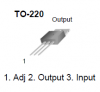
(1) Firstly, as Keep says above, you need to add a rectifier diode for protection: for example 1N400x (where x is any number) cathode to the LM317 input pin and anode to the LM317 output pin.
(2) Also as Keep says, there is a minimum current output for the LM317. This minimum current is 10mA, so the resistor between adjust and output should be 120 Ohms maximum not 330 Ohms. 100 Ohms will be fine.
(3) The length of leads and layout are important (the LM317 is a high gain, high current amplifier) to avoid oscillations. Can you post a picture of your physical circuit?
(4) The type of capacitors are also important for good decoupling. In order of preference, they should be, ceramic, polypropylene metalized film, or low-loss aluminum electrolytic.
(5) Use substantial interconnecting wires- not thin. This is to ensure a low impedance which will help prevent oscillations and also improve voltage regulation.

To test your LM317 regulators do the following:
(1) Get a 9V PP3 style battery.
(2) Get a 100 Ohm resistor.
(3) Get a 22 Ohm resistor.
(4) Get a 100nF or higher ceramic capacitor.
(5) Connect the capacitor between the regulator input and adjust (use as short a leads as possible).
(6) Connect the 100 Ohm resistor between output and adjust (use as short leads as possible).
(7) Connect the battery positive to input and and negative to adjust (use as short leads as possible) .
(8) The voltage between the LM317 output and sense should be between 1.2V and 1.3V (1.25V nominal).
(9) Connect a 22 Ohm resistor between the output and adjust.
(10) The voltage between the output pin and adjust should be unchanged from the reading of (8) above.

spec

LM317 Datasheet
https://www.ti.com/lit/ds/symlink/lm317.pdf
IN400x Rectifier Diode Datasheet
https://www.vishay.com/docs/88503/1n4001.pdf
 
Last edited:
Oops! - 220
Hy Keep,

As I have changed post #14 the item line is now (9) rather than (6).

No, 22 Ohms is correct; it is just a load to draw around 54 mA extra to ensure that the LM317 is regulating.

Good to know you are checking though.:)

spec
 
Last edited:
I don't know why your circuit burned, I have use RF-637V trimpot but no significant heat up. Might check the tab and heatsink because tab are connected to the tab.
Tell me when the pot start to heat up and burn? I mean how many Ohms? The pot you used can't burn until power dissipation over 1W .
 
I don't know why your circuit burned, I have use RF-637V trimpot but no significant heat up. Might check the tab and heatsink because tab are connected to the tab.
Tell me when the pot start to heat up and burn? I mean how many Ohms? The pot you used can't burn until power dissipation over 1W .
when it is less than 1500 ohm approximately ... and in 1500 to 5000 ohm the output voltage is 16.50v
 
Just a note:
In this configuration, the current of the potentiometer is fixed, practically speaking.

I_pot = V21 / 330 = about 3.7 mA (I_adj of pin 1 is very small).

This current didn't damage even the mini-potentiometer I may use on the board of my regulators.

And since this current also supplies the internal circuit of LM317, I usually increase it a bit and use 220 Ohm instead.
 
Status
Not open for further replies.

Latest threads

New Articles From Microcontroller Tips

Back
Top