Here's a circuit that performs two functions which, at first glance, might appear rather difficult to do with one wire. The circuit uses a momentary push-button switch to change the state of a remote bistable relay circuit along with a switch-located LED indication of the relay state. The LED is lit only when the relay is energized but requires only one wire between the switch and relay for both relay and LED control (along with power and chassis ground, of course) with no added circuitry at the switch.
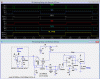
Below is an LTspice simulation of the circuit:

The key to the circuit operation is transistor Q1 which detects the current from the relay driver to the switch LED when the relay is energized. This LED current saturates the transistor, causing a voltage high at Node 3. This means both inputs to the XOR gate are high which makes its output low.
When the PB is pressed, the current from the relay driver to the LED stops (since the LED current is now supplied by the PB voltage). The transistor then turns off, dropping the Node 3 voltage to 0V.
Since one input to the XOR gate U3 is now low, its output goes high, generating a clock pulse which triggers the toggle flip-flop U2 to the OFF relay/LED state. (Note that the LED doesn't go off until the PB is released.)
(C1, R3, and D3 are for switch debounce.)
With the relay off, both Nodes 1 and 3 are low, so the XOR output is again low. Pushing the PB momentarily again, raises the Node 1 voltage which causes the XOR gate to generate another high clock pulse, triggering U2 back to the relay ON state.
(D2 prevents reverse-bias base-emitter breakdown when the PB is pressed in the relay OFF state).
C3 and R5 generate a signal to set the FF to the relay OFF state upon power up.
It might seem that there is a missing transient suppression diode across the relay coil but that's not needed with an emitter follower driving the relay.
Upon transistor turn-off, the inductive current will simply pull the emitter voltage low enough (≈-0.7V) to keep the transistor on until the current has decayed to zero. Looking at the relay coil voltage shows this.
The circuit can be controlled by more than one PB in parallel.
All the PB LEDs will indicate the state of the relay.
Note that the power and ground pins for the FF and XOR gate are not shown and must be connected.
Also all the unused inputs (not outputs) for the other XOR gates and FF in the packages must be tied to ground.
P.S. See the Updates for an alternate circuit that will operate from a grounded PB and a modification that uses a high-side MOSFET switch instead of a relay.
Below is an LTspice simulation of the circuit:
The key to the circuit operation is transistor Q1 which detects the current from the relay driver to the switch LED when the relay is energized. This LED current saturates the transistor, causing a voltage high at Node 3. This means both inputs to the XOR gate are high which makes its output low.
When the PB is pressed, the current from the relay driver to the LED stops (since the LED current is now supplied by the PB voltage). The transistor then turns off, dropping the Node 3 voltage to 0V.
Since one input to the XOR gate U3 is now low, its output goes high, generating a clock pulse which triggers the toggle flip-flop U2 to the OFF relay/LED state. (Note that the LED doesn't go off until the PB is released.)
(C1, R3, and D3 are for switch debounce.)
With the relay off, both Nodes 1 and 3 are low, so the XOR output is again low. Pushing the PB momentarily again, raises the Node 1 voltage which causes the XOR gate to generate another high clock pulse, triggering U2 back to the relay ON state.
(D2 prevents reverse-bias base-emitter breakdown when the PB is pressed in the relay OFF state).
C3 and R5 generate a signal to set the FF to the relay OFF state upon power up.
It might seem that there is a missing transient suppression diode across the relay coil but that's not needed with an emitter follower driving the relay.
Upon transistor turn-off, the inductive current will simply pull the emitter voltage low enough (≈-0.7V) to keep the transistor on until the current has decayed to zero. Looking at the relay coil voltage shows this.
The circuit can be controlled by more than one PB in parallel.
All the PB LEDs will indicate the state of the relay.
Note that the power and ground pins for the FF and XOR gate are not shown and must be connected.
Also all the unused inputs (not outputs) for the other XOR gates and FF in the packages must be tied to ground.
P.S. See the Updates for an alternate circuit that will operate from a grounded PB and a modification that uses a high-side MOSFET switch instead of a relay.