Electro Tech is an online community (with over 170,000 members) who enjoy talking about and building electronic circuits, projects and gadgets. To participate you need to register. Registration is free. Click here to register now.
Welcome to our site! Electro Tech is an online community (with over 170,000 members) who enjoy talking about and building electronic circuits, projects and gadgets. To participate you need to register. Registration is free. Click here to register now.
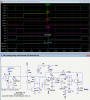
Here's a modification to the circuit that allows the remote control and indication of a latching relay circuit using a single wire with the PB connection to ground, thus requiring no power or added circuitry at the PB.
It requires one 4013 flip-flop package and two transistors.
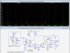
Below is the LTspice simulation of the circuit:
When the relay is ON, current flows through D2 and R7 to light the LED indicator at the PB. This voltage also saturates Q1 so the outputs at Node 3 and the Clk are low.
Momentarily pushing the PB grounds Node 1 which turns off Q1, generating a positive clock pulse to trigger the flip-flop and toggle it to the relay OFF state.
The voltage at Node 1 is now about 1.5v as determined by R6 and R8. D2 prevents the relay coil from shorting the voltage to ground. This voltage is enough to again saturate Q1 but is below the minimum turn-on voltage of most common LEDs so the indicator LED is not lit.
Momentarily pushing the PB again turns off Q1, generating another clock pulse which toggles the FF back to the relay ON state.
C1 provides the debounce function for the PB switch.
U2 flip-flop is configured to generate a clean clock-pulse from the slow rise-time signal across C1. (The 4013 generates a high at its Q output when both PRE and CLR inputs are high).
R3 and D3 provide positive feedback to generate hysteresis and prevent any clock glitches.
R7 limits the current when Node 1 is grounded by the PB.
This circuit can also be controlled by more than one PB in parallel.
All the PB LEDs will indicate the state of the relay.
Note that the power and ground pins for the FF and Schmitt trigger packages are not shown and must be connected.
This site uses cookies to help personalise content, tailor your experience and to keep you logged in if you register.
By continuing to use this site, you are consenting to our use of cookies.