*DISCLAIMER* THIS PROJECT WORKED 100% FOR ME, I HOPE IT WORKS FOR YOU TOO. BUT I CAN NOT SUPERVISE YOU WHILE BUILDING THIS, SO I CAN NOT GUARANTY YOU WILL DO IT RIGHT. AND ALTHOUGH I HAVE GONE OVER THESE INSTRUCTIONS CAREFULLY TO MAKE SURE THEY ARE ACCURATE, I AM HUMAN AND I MAKE MISTAKES. THEREFOR I AM NOT RESPONSIBLE FOR ANY DAMAGES OR INJURIES CAUSED BY FOLLOWING THESE INSTRUCTIONS. IT IS YOUR RESPONSIBILITY TO MAKE SURE YOU DO THINGS SAFELY. IF YOU ARE DOING THIS AND ARE UNDER THE AGE OF 18, YOU MUST HAVE A PARENT OR GUARDIAN HELPING YOU AT ALL TIMES. IF YOU DO NOT ACCEPT AND AGREE TO EVERY PART OF THIS THEN STOP READING HERE.
Overview
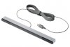
With the introduction of the Nintendo Wii came one of the most interesting remote controls to ever be designed. The "Wiimote". These fascinating devices use a digital camera inside the controller it's self to be able to tell where you are pointing them. Also they have a MEMS sensor that let them detect both movement, and tilt. And with a typical Bluetooth dongle and the right software, you can even use one of these controllers with your PC.
There is just one catch. To make them work, you need to have a special light bar pointing at the remote...

Thankfully, A nice looking USB powered light bar can be made in the home for very cheep and without much hassle. This light bar also has the advantage that it will work just as well with your PC as it will with your Wii. And if that wasn't good enough, you can adjust the space between the two lights to fit any usage scenario. Which is something you can't do with a stock Wii light bar.

Here are some step by step instructions with pictures. You may modify these instructions based on your particular skill level and materials.
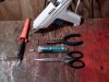
Equipment.
Soldering Iron, and electrical solder.
Hot glue gun with plenty of glue.
A pair of cruddy scissors.
A pair of needle nosed pliers.
One round pointed implement.
A multimeter. (*Optional)
Digital camera (Not shown because it was being used.)

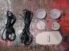
Materials
One(1) junk USB cable.
Six(6) Infra red LEDs.
Two(2) 100 Ohm 1/4 watt resistors.
Two(2) clear plastic beverage lids.
Double strand speaker wire.
Thin cereal box cardboard.
Several magnets. (*Optional)

Step One, The USB cord.
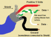
We are using the USB port as nothing more than a convenient 5 volt power supply to light our LEDs up. So the first thing you need to do is get the free end of your junk USB cord attached to two lengths of speaker wire. To do this, you need to know which wire on your cord is the five volt and which is the ground. Luckily there are many ways to figure this out. By far the easiest way is to cut the end off your cord and strip back the wires and look at them. Almost every USB cord in existence follows the same color code to the letter. That is...

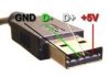
If for some reason the cords are not colored as above, or you're not 100% sure. You can also use a multimeter to test the wires. The safest way is to put one probe on one wire, and the other probe on the different contacts of the connector and read the continuity (conductivity). When looking at the connector from the end, with the plastic part that has the contacts embedded into it on the bottom, the positive 5 volt pin is all the way to the right. And the ground pin is all the way to the left. You can also use the shield as the ground, as they both connect to the same place in the end. Here is an image of that...
(Note: D+ and D- happen to be wrong in this image.)

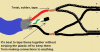
Once you have figured out which wires are which. You need to connect two lengths of your speaker wire to your cable. One half of each wire should go to the red/positive 5 volt wire, and the other to the shield/black wire. Make sure you have each half of your two lengths of wire connected to each of the two power wires. AND DON'T connect the power wires to each other. You want to have a 5 volt and ground running one way, and a 5 volt and ground running the other way. DON'T make two grounds going one way, and two 5 volts going the other way, that won't work. I usually connect the white striped side of my speaker wire to the positive, and the non-striped side to the ground. Like so...

My particular USB cable was an old cell phone charging cable which I didn't need anymore. I got lucky with my cable because the connector at the end would come apart and give me access to the power wires without me having to strip anything. I made the two speaker wires join together with the power wires at this point.

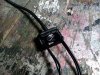
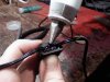
After my two lengths of speaker wire were soldered to the power wires, and all the other wires were cut and taped so they couldn't short out on anything. I closed up the two halves of what was the end connector and filled the void with hot glue.

It is possible that you don't have such a cable that you can do this with, that's fine. All you need to know is that you need to connect one half of each length of your speaker wire to each of the power wires. Then you need to insulate them from each other and cover the whole thing up. You can use any small hollow object filled with hot glue in place of the end connector that I had. Or you can just use electrical tape if you would prefer.
Step two, Making the lights.
The next step will be to make the two light circuits, and attach them to our two lengths of USB powered speaker wire. The light circuit is supper simple. All we are doing is connecting three infra red LEDs together in series (one, into the other, into the other.) and then attaching a current limiting resistor on them to prevent them from being over powered. For a circuit board, we will be using cereal box cardboard.
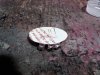
First, trace out a circle on your cardboard with your clear beverage lids as a template. You will also want to trim the circle down about a millimeter so they fit inside the lids all the way down to the bottom.

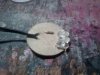
Next, you'll want to arrange your LEDs on your cardboard so they don't go over the edge. You want to fan them out a bit so that the light can be seen from a fairly wide angle. Somewhat like this...
(Note: It doesn't have to be perfect, we can adjust them later.)

You need to poke holes in the cardboard where the LED pins need to go though it. You shouldn't use the pins of the actual LEDs for poking the holes, as they can break really easily. Use something else like a thumbtack to poke your holes instead. You need to poke two holes for each part. 6 holes for your LEDs, two for your resistor, and two holes for your speaker wire.

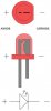
Next, you will need to put all your parts on the board, and solder them to each other. !!SUPER IMPORTANT!! LEDs have a polarity. That is, they will only light up if you hook the positive up to the longer pin (non flat side) and the negative wire up to the short pin (flattened side). Another way to tell, is to look through the plastic. The wire connected to the bigger piece is the ground, and the smaller side is the positive. If you get this wrong, it will not work. Here is an image to help you out...

So, you need to solder the positive of one LED, to the negative of another, and keep doing this until you have one positive and one negative left for a chain of three LEDs. Then you just solder your resistor on to either end of the chain. With the resistor, it doesn't matter which side or direction you connect it because resistors don't have a polarity like LEDs do. Finaly, after you have done the above, you will want to solder your power wires to your chain of parts. It is important to know that this too must be attached the right way. You need to know or remember which of your wires is positive, and which is negative. As I said above. I personally attach the white stripe side of my speaker wire to the positive of the USB cable. In the end, the result should look something like this...


Step Three, testing.
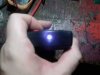
With all the things that can go wrong up until now, it may be somewhat necessary to be able to test to see if this thing is actually making light. Sadly, the human eye can't see infra red. But as fortune would have it, almost all digital cameras can see IR LEDs, even a cheep camera phone.

Point your digital camera at a TV remote look at the display screen, then press a few buttons on the remote. The display screen should light up just like above. If not, either use a different camera, or make sure the remote has batteries and actually works. If you see something on the screen, then you know that your camera can see infra red. Now it's time to test your light bar circuit. Plug in the USB cord to a computer or USB charger for just a second. Hopefully, if you didn't screw up badly. Nothing should short out and your computer or charger shouldn't blow up. If nothing shorted out, but you don't see any light in your cameras view finder like above, then you only screwed up a little bit.
First, you should check that all of your LEDs are the right way around, as this is the most likely problem. All LEDs need to have their positive pins on the positive side of the chain, and the ground pins on the ground side. Secondly, check that you attached your speaker wires to the LEDs and to the USB cable the correct way. This is easiest to test with a multimeter on voltage mode if you have one handy. Next check that all of your connections are reasonably well soldered where they should be soldered. The solder should flow into and around the connections, taking their shape. It should NOT ball up on the side of the wire or flake off easy. Picking at the connections with a point implement or pulling on them gently is a good way to find cold solder joints by eye. Finally, look for short connections, which are metal to metal connections that shouldn't be connected. Such as the resistor being connected to both the positive power wire, and the ground power wire.
80% of the time, it's that you have an LED backwards, tipple check this.
15% of the time, you have the power wires backwards or just plain wrong.
The other 5% is odd ball stuff like connections being bad and such.
If you payed attention to the way things are wired, especially the LEDs, then you should have had the lights lit up on the first try. Good job")
Step four, packaging up the lights.
At this point you have something that makes the right light, but it is not very safe or pretty. It's just a bare circuit. So now, we are going to put it in some nice looking packaging.
First, you want to melt a spot down on the edge of your two clear beverage lids. This is to make room for your speaker wires, so make sure it is just deep enough for the wire. Make sure your whole light circuit can fit in under the lid with the lid open end down on a flat surface. The lid should not rock, as this would indicate an uneven surface. If it all does fit well, flip it back over and remove the circuit.
Your going to want to do the next steps fairly fast, so read them over a few times and prepare every thing before you actually attempt it all. And be careful not to burn yourself while doing this. A small bucket of cold water is handy for when you get some glue on your hand.
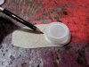
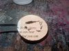
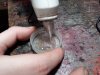
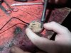
Begin by filling the lid with a bunch of hot glue...

You want to get the lid about 2/3 of the way full, then you want to quickly put the light circuit back into the cap just as before, smashing it into the still hot glue...

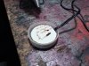
Then you want to quickly back fill over the circuit the rest of the way with more hot glue...

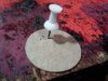
While the glue is still hot, stick in the magnets...

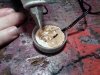
If you want, you could use something else like Velcro, buttons, hooks, or whatever you feel is best for your environment. We used magnets because this was going on top of a sound system with a metal cover. Take this part of the project on a case by case basis. Case in point, we had a problem with alignment with our magnets. We fixed this by using the soldering iron and heating them, which remelted the hotglue around them enough to allowed us to move them again...

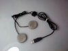
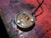
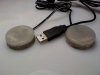
Final steps
After things cool, you need to do most of the steps above again for the other light circuit and lid. When you're done you should end up with a decent looking Light bar for your Wii or PC, Enjoy.

Overview
With the introduction of the Nintendo Wii came one of the most interesting remote controls to ever be designed. The "Wiimote". These fascinating devices use a digital camera inside the controller it's self to be able to tell where you are pointing them. Also they have a MEMS sensor that let them detect both movement, and tilt. And with a typical Bluetooth dongle and the right software, you can even use one of these controllers with your PC.
There is just one catch. To make them work, you need to have a special light bar pointing at the remote...
Thankfully, A nice looking USB powered light bar can be made in the home for very cheep and without much hassle. This light bar also has the advantage that it will work just as well with your PC as it will with your Wii. And if that wasn't good enough, you can adjust the space between the two lights to fit any usage scenario. Which is something you can't do with a stock Wii light bar.
Here are some step by step instructions with pictures. You may modify these instructions based on your particular skill level and materials.
Equipment.
Soldering Iron, and electrical solder.
Hot glue gun with plenty of glue.
A pair of cruddy scissors.
A pair of needle nosed pliers.
One round pointed implement.
A multimeter. (*Optional)
Digital camera (Not shown because it was being used.)
Materials
One(1) junk USB cable.
Six(6) Infra red LEDs.
Two(2) 100 Ohm 1/4 watt resistors.
Two(2) clear plastic beverage lids.
Double strand speaker wire.
Thin cereal box cardboard.
Several magnets. (*Optional)
Step One, The USB cord.
We are using the USB port as nothing more than a convenient 5 volt power supply to light our LEDs up. So the first thing you need to do is get the free end of your junk USB cord attached to two lengths of speaker wire. To do this, you need to know which wire on your cord is the five volt and which is the ground. Luckily there are many ways to figure this out. By far the easiest way is to cut the end off your cord and strip back the wires and look at them. Almost every USB cord in existence follows the same color code to the letter. That is...
If for some reason the cords are not colored as above, or you're not 100% sure. You can also use a multimeter to test the wires. The safest way is to put one probe on one wire, and the other probe on the different contacts of the connector and read the continuity (conductivity). When looking at the connector from the end, with the plastic part that has the contacts embedded into it on the bottom, the positive 5 volt pin is all the way to the right. And the ground pin is all the way to the left. You can also use the shield as the ground, as they both connect to the same place in the end. Here is an image of that...
(Note: D+ and D- happen to be wrong in this image.)
Once you have figured out which wires are which. You need to connect two lengths of your speaker wire to your cable. One half of each wire should go to the red/positive 5 volt wire, and the other to the shield/black wire. Make sure you have each half of your two lengths of wire connected to each of the two power wires. AND DON'T connect the power wires to each other. You want to have a 5 volt and ground running one way, and a 5 volt and ground running the other way. DON'T make two grounds going one way, and two 5 volts going the other way, that won't work. I usually connect the white striped side of my speaker wire to the positive, and the non-striped side to the ground. Like so...
My particular USB cable was an old cell phone charging cable which I didn't need anymore. I got lucky with my cable because the connector at the end would come apart and give me access to the power wires without me having to strip anything. I made the two speaker wires join together with the power wires at this point.
After my two lengths of speaker wire were soldered to the power wires, and all the other wires were cut and taped so they couldn't short out on anything. I closed up the two halves of what was the end connector and filled the void with hot glue.
It is possible that you don't have such a cable that you can do this with, that's fine. All you need to know is that you need to connect one half of each length of your speaker wire to each of the power wires. Then you need to insulate them from each other and cover the whole thing up. You can use any small hollow object filled with hot glue in place of the end connector that I had. Or you can just use electrical tape if you would prefer.
Step two, Making the lights.
The next step will be to make the two light circuits, and attach them to our two lengths of USB powered speaker wire. The light circuit is supper simple. All we are doing is connecting three infra red LEDs together in series (one, into the other, into the other.) and then attaching a current limiting resistor on them to prevent them from being over powered. For a circuit board, we will be using cereal box cardboard.
First, trace out a circle on your cardboard with your clear beverage lids as a template. You will also want to trim the circle down about a millimeter so they fit inside the lids all the way down to the bottom.
Next, you'll want to arrange your LEDs on your cardboard so they don't go over the edge. You want to fan them out a bit so that the light can be seen from a fairly wide angle. Somewhat like this...
(Note: It doesn't have to be perfect, we can adjust them later.)
You need to poke holes in the cardboard where the LED pins need to go though it. You shouldn't use the pins of the actual LEDs for poking the holes, as they can break really easily. Use something else like a thumbtack to poke your holes instead. You need to poke two holes for each part. 6 holes for your LEDs, two for your resistor, and two holes for your speaker wire.
Next, you will need to put all your parts on the board, and solder them to each other. !!SUPER IMPORTANT!! LEDs have a polarity. That is, they will only light up if you hook the positive up to the longer pin (non flat side) and the negative wire up to the short pin (flattened side). Another way to tell, is to look through the plastic. The wire connected to the bigger piece is the ground, and the smaller side is the positive. If you get this wrong, it will not work. Here is an image to help you out...
So, you need to solder the positive of one LED, to the negative of another, and keep doing this until you have one positive and one negative left for a chain of three LEDs. Then you just solder your resistor on to either end of the chain. With the resistor, it doesn't matter which side or direction you connect it because resistors don't have a polarity like LEDs do. Finaly, after you have done the above, you will want to solder your power wires to your chain of parts. It is important to know that this too must be attached the right way. You need to know or remember which of your wires is positive, and which is negative. As I said above. I personally attach the white stripe side of my speaker wire to the positive of the USB cable. In the end, the result should look something like this...
Step Three, testing.
With all the things that can go wrong up until now, it may be somewhat necessary to be able to test to see if this thing is actually making light. Sadly, the human eye can't see infra red. But as fortune would have it, almost all digital cameras can see IR LEDs, even a cheep camera phone.
Point your digital camera at a TV remote look at the display screen, then press a few buttons on the remote. The display screen should light up just like above. If not, either use a different camera, or make sure the remote has batteries and actually works. If you see something on the screen, then you know that your camera can see infra red. Now it's time to test your light bar circuit. Plug in the USB cord to a computer or USB charger for just a second. Hopefully, if you didn't screw up badly. Nothing should short out and your computer or charger shouldn't blow up. If nothing shorted out, but you don't see any light in your cameras view finder like above, then you only screwed up a little bit.
First, you should check that all of your LEDs are the right way around, as this is the most likely problem. All LEDs need to have their positive pins on the positive side of the chain, and the ground pins on the ground side. Secondly, check that you attached your speaker wires to the LEDs and to the USB cable the correct way. This is easiest to test with a multimeter on voltage mode if you have one handy. Next check that all of your connections are reasonably well soldered where they should be soldered. The solder should flow into and around the connections, taking their shape. It should NOT ball up on the side of the wire or flake off easy. Picking at the connections with a point implement or pulling on them gently is a good way to find cold solder joints by eye. Finally, look for short connections, which are metal to metal connections that shouldn't be connected. Such as the resistor being connected to both the positive power wire, and the ground power wire.
80% of the time, it's that you have an LED backwards, tipple check this.
15% of the time, you have the power wires backwards or just plain wrong.
The other 5% is odd ball stuff like connections being bad and such.
If you payed attention to the way things are wired, especially the LEDs, then you should have had the lights lit up on the first try. Good job
Step four, packaging up the lights.
At this point you have something that makes the right light, but it is not very safe or pretty. It's just a bare circuit. So now, we are going to put it in some nice looking packaging.
First, you want to melt a spot down on the edge of your two clear beverage lids. This is to make room for your speaker wires, so make sure it is just deep enough for the wire. Make sure your whole light circuit can fit in under the lid with the lid open end down on a flat surface. The lid should not rock, as this would indicate an uneven surface. If it all does fit well, flip it back over and remove the circuit.
Your going to want to do the next steps fairly fast, so read them over a few times and prepare every thing before you actually attempt it all. And be careful not to burn yourself while doing this. A small bucket of cold water is handy for when you get some glue on your hand.
Begin by filling the lid with a bunch of hot glue...
You want to get the lid about 2/3 of the way full, then you want to quickly put the light circuit back into the cap just as before, smashing it into the still hot glue...
Then you want to quickly back fill over the circuit the rest of the way with more hot glue...
While the glue is still hot, stick in the magnets...
If you want, you could use something else like Velcro, buttons, hooks, or whatever you feel is best for your environment. We used magnets because this was going on top of a sound system with a metal cover. Take this part of the project on a case by case basis. Case in point, we had a problem with alignment with our magnets. We fixed this by using the soldering iron and heating them, which remelted the hotglue around them enough to allowed us to move them again...
Final steps
After things cool, you need to do most of the steps above again for the other light circuit and lid. When you're done you should end up with a decent looking Light bar for your Wii or PC, Enjoy.
-
 nintendo-wii-sensor-bar.jpg
 -
 1211012245.jpg
 -
 1211011950a.jpg
 -
 1211011950.jpg
 -
 USB.png
 -
 imgres.jpg
 -
 How to wire.png
 -
 1211012011.jpg
 -
 1211012015.jpg
 -
 1211011954.jpg
 -
 1211012034a.jpg
 -
 1211012011a.jpg
 -
 LED polarity.jpg
 -
 1211012028.jpg
 -
 1211012029a.jpg
 -
 0924020320.jpg
 -
 1211012123.jpg
 -
 1211012125.jpg
 -
 1211012125b.jpg
 -
 1211012127a.jpg
 -
 1211012128.jpg
 -
 1211012247.jpg
