I want to discuss a component that does not get a lot of publicity in the electronics world. I am talking about the constant current diode. Perhaps some of you are not aware that there is such a device. It is certainly difficult to procure and only a few distributors carry it in stock. Mouser.com is one distributor where you may be able to obtain constant current diodes at various current values.
A constant current diode does exactly as is implied: it provides a constant current between a voltage source and the load no matter what the load resistance may be (up to a limit). For instance, if a 1mA constant current diode is in series with a 12 volt source and a load resistor, then the resistance of the resistor can vary from 0 Ohms to almost 12K Ohms (probably 10K Ohms practically), and the current around the loop will remain 1mA.
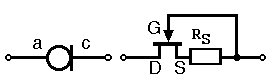
A constant current diode is usually constructed from a junction field effect transistor (JFET) and a resistor that sets the device current output (see schematic symbol below).
A practical use for a constant current diode might be in an optical isolator circuit (see partial schematic OptoIsolEight.pdf). When designing electronics for general usage, it is usually a good idea to make it as robust as possible; no one knows for sure what the user will connect to it in all circumstances. Therefore, it’s best to provide the greatest flexibility possible and accommodate the widest range of inputs.
In the schematic, 8 switch closures are being monitored. However, the switches themselves may be far away from the optical isolators and the wiring could represent a significant resistance to the loop and vary from installation to installation. A constant current diode will automatically adjust for this variable resistance and provide proper current flow to the optical isolators under many conditions. The optical isolator outputs are fed to a de-bouncer circuit consisting of RC elements and a Schmitt Trigger before the signals are sent to a microcontroller. Optional diagnostic LEDs are included so that the user can quickly tell the state of the connected switches. The isolated DC to DC converter makes sure that even the grounds are isolated from the microcontroller board.
A constant current diode does exactly as is implied: it provides a constant current between a voltage source and the load no matter what the load resistance may be (up to a limit). For instance, if a 1mA constant current diode is in series with a 12 volt source and a load resistor, then the resistance of the resistor can vary from 0 Ohms to almost 12K Ohms (probably 10K Ohms practically), and the current around the loop will remain 1mA.
A constant current diode is usually constructed from a junction field effect transistor (JFET) and a resistor that sets the device current output (see schematic symbol below).
A practical use for a constant current diode might be in an optical isolator circuit (see partial schematic OptoIsolEight.pdf). When designing electronics for general usage, it is usually a good idea to make it as robust as possible; no one knows for sure what the user will connect to it in all circumstances. Therefore, it’s best to provide the greatest flexibility possible and accommodate the widest range of inputs.
In the schematic, 8 switch closures are being monitored. However, the switches themselves may be far away from the optical isolators and the wiring could represent a significant resistance to the loop and vary from installation to installation. A constant current diode will automatically adjust for this variable resistance and provide proper current flow to the optical isolators under many conditions. The optical isolator outputs are fed to a de-bouncer circuit consisting of RC elements and a Schmitt Trigger before the signals are sent to a microcontroller. Optional diagnostic LEDs are included so that the user can quickly tell the state of the connected switches. The isolated DC to DC converter makes sure that even the grounds are isolated from the microcontroller board.

