Continue to Site

Welcome to our site!

Electro Tech is an online community (with over 170,000 members) who enjoy talking about and building electronic circuits, projects and gadgets. To participate you need to register. Registration is free. Click here to register now.

  • Welcome to our site! Electro Tech is an online community (with over 170,000 members) who enjoy talking about and building electronic circuits, projects and gadgets. To participate you need to register. Registration is free. Click here to register now.

Yet Another ICD2 Emulator

Status
Not open for further replies.
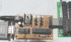
Yup it's another ICD2 clone. It's about as simple as I could design it. The power supply (not shown) is a 5V DC switching wall wart and cost me $2 from a surplus store in Toronto.

I used a 16F876 (not A) with microchips firmware and it passes all self tests. I've designed it with a weedy power stealing VPP from the MAX232 (with big 10uf caps) and a 1.5x multiplier (the diodes and such bring it down to approx 12.8V)

Looking at the scads of ICD2 clones on the net and the might work might not modded firmware for the 16F876A I stuck with the still available 16F876 (If you've got working 16F876A firmware let me know)

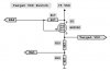
The Lothar Stolz ICD2 clone is very good **broken link removed** , it's the basis of this one (the Inchworm). Only real change is the power supply and LEDs. I haven't tried his LM358 op-amp version. I don't see how it generates all three states for VPP. (12.5V target VPP, 5V target run, 0V reset)

Comments & flames welcome :)
 

Attachments

  • Inchworm ICD2.gif
    Inchworm ICD2.gif
    45.1 KB · Views: 1,063
Last edited:
cute design for Vpp but wont the drop across Q2 take it below the level needed for some PICs?

I've done a simulation of the op amp part of lothar's circuit and it does, indeed, generate the proper 3 Vpp states. if you want I can send you the Switcher Cad file. You would need a Rail to Rail opamp if you fed it 12.8V. The 358 doesn't cut it in that case.

I got lothar's opamp design working with the 877A so I believe the 876A should work, too. You just need the ICD661.hex bootloader instead of the one that ships with MPLAB.
 
Any pictures of the completed project Bill?

I added a Target VDD high-side switch to allow ICD2 powered Target VDD (an option in the ICD2 menu).

I've used both the '876 and the '876A (with modified bootloader file below which should be renamed with ".hex" filename extension) and they work exactly the same.

Regards, Mike
 

Attachments

  • ICD2 Clone #2.JPG
    ICD2 Clone #2.JPG
    40.1 KB · Views: 690
  • Target VDD Switch Final.jpg
    Target VDD Switch Final.jpg
    23.3 KB · Views: 528
  • ICD2_Bootloader_A.txt
    3 KB · Views: 443
Last edited:
Full speed ICD2 clone using PIC4550 now available
Compare to the serial version you actually can do real time debug.

**broken link removed**

I build one and it works much faster than serial or USB to serial version using FT232

I used TQFP ICs so it fits in a small box.
 
Last edited:
Andy_123 said:
Full speed ICD2 clone using PIC4550 now available
Compare to the serial version you actually can do real time debug.

**broken link removed**

I build one and it works much faster than serial or USB to serial version using FT232

I used TQFP ICs so it fits in a small box.
Just read through all 16 pages yesterday and ordered 18F4550 samples today. A wonderful detective story (grin). Bravo to those few guys who figured out the mystery of the 18F4550 bootloader. I'd love to look at your schematic but the file's not mirrored yet and I don't want to use my points. The cabinet/case looks very nice though, just like your previous version I believe.

Please take care. Kind regards, Mike
 
Here is a "Mirror" of my version, same box, same PCB size.
 

Attachments

  • ICD2-4550-TQFP.zip
    611.8 KB · Views: 614
Andy_123 said:
Here is a "Mirror" of my version, same box, same PCB size.

Thank you Sir. Never have quite figured out the motivation for that download point system on the EDABoard. Regards, Mike
 
I don't understand these points also, where they are coming from?
I guess I never had this issue ;)

I will be ordering factory made boards for my design in a couple weeks and hoping to make TQFP "socket" this weekend so I can program ICs offline.
But board included ICSP headres as well.
 
I haven't tried his LM358 op-amp version. I don't see how it generates all three states for VPP. (12.5V target VPP, 5V target run, 0V reset)
It works very simple:
Uses 3 input combinations to get 3 modes:

Off = 0V
Repeater mode= 5V (5V from the input = 5V out)
Amp mode = Vpp (based on resistor ratio and PS voltage)
 
Andy_123 said:
I don't understand these points also, where they are coming from?
I guess I never had this issue ;)

the whole point of points is to reward helpfull people and/or generate revenue by people purchasing them. wierd but it has a ceartain appeal.

they do some other odd things like obfuscate URLs ( h**p instead of http). their excuse for doing it is for "user security" Seems kind of a lame answer.

sadly, the "student" content is about 10X of this board. You think we get some vague questions here...
 
ok, I've looked at the 4550 based versions. the 4550 is just being a USB port. I made a version of lothar's design using a Ft232RL. That seems a lot simpler to me.
 
The '4550 is used in Microchip's "new" ICD2 to replace the USB-to-Parallel Cypress chip and is much faster than the FT232 when running the ICD2 with a target in "debug" mode.
 
philba,
As I built and published 4 different versions of these clones, I have something to compare:

All FT version as well as serial version are working great and simple if you use them as a programmer.
For programmer it does not matter how long it takes to program the chip: 3 second or 20 seconds.

But the main goal of ICD is DEBUGGING.
To be honest, FT version makes debugging impossible. It takes 20-30 second between steps and this is un aceptable.
With 4550 version they are not depending on 57.6 communication speed of the port and pumping data via streaming parallel port on 4550
I tested debugging on 18f452 and it takes only 1-2 second per step. It probably will be less if you use a powerfull PC.

With cost of components almost the same, where is no reason anymore to build FT versions.
 
Hi guys,

I agree with Andy. If you're lookin' for a simple "programmer only" USB design then I would suggest building a PICKit 2 clone using the 18F2550. Updated software and support within the MPLAB IDE is expected soon.

Regards, Mike
 
Hi,

thanks for posting the schematics Andy!

Anyone tried to optically isolate the programmer? When programming dspics on a power electronic device it would be nice to have galvanic separation of the computer and the target device. It would be the easiest to do that on the USB side because there are only 2 unidirectional lines there, but those are the ones running at the highest speed... USB runs at 48MHz if I'm not mistaken?

Andi
 
Isolated verson:
It is possible, actually you will need to isolate 0V and 5V as well.

For power isolation you can use DCP01 similar that I am using to get +15V

For TQFP users:
I made offline TQFP programmer last night, so pre-porgrammed TQFP ICs available now!
 
Hi,

yes of course. I think I would supply the entire circuit from the target board and isolate at the USB side, I just don't think optocouplers are fast enough? Maybe I would better place the isolation right before the target connector? But then PGD is bidirectional which makes the whole thing more complex.

Andi
 
Just an update on the Inchworm ICD2 emulator.

www.myblueroom.com for the schematic

The VPP using the MAX232 is 12.3VDC (using 1N4148s) if you think you need more use 1N5817 diodes instead. It has no problem programming 16F877 & 16F88. The cost of all the parts should be under $25

The idea of having even a most basic ICD albeit a slow one is far better than just a programmer. It can be hand wired in an afternoon and even a one time programmer can be protoboarded together in short order (Program the 16F876 bootloader with something really simple like this) http://www.geocities.com/jpadfield13/noppp3.html

Then program another 16F876 bootloader with your new ICD2 emulator (using the Microchip algorithms) It's also a good idea to keep a programmed spare just incase.

There are no regulators in the design as 5VDC regulated wall adapters are becoming more common (many cell phone chargers use them) I've bought a few from a local surplus store for $2 each 5VDC @ 2A
Markings are
Model SPS10A-001 (TSA-0285)
I.T.E. Power Supply
1.3mm coax plug tip positive
 
Status
Not open for further replies.

Latest threads

Back
Top