Smartie
Member
Hey guys,
Update: Bit of a mistake, its a MCP4922 not MCP1922. sorry
Last week I ordered some sample components from Microchip and got them in the mail two days ago.
I got 2 MCP1922 (dual 12 DAC) and 2 24FC512 (64KByte EEPROM)
I'm trying to get the DACs working at the moment but I'm having a few problems.
I've followed the data sheet and set up the circuit accordingly, I'm sure I'm sending the the SPI commands and I'm sure I have the correct voltage levels set up.
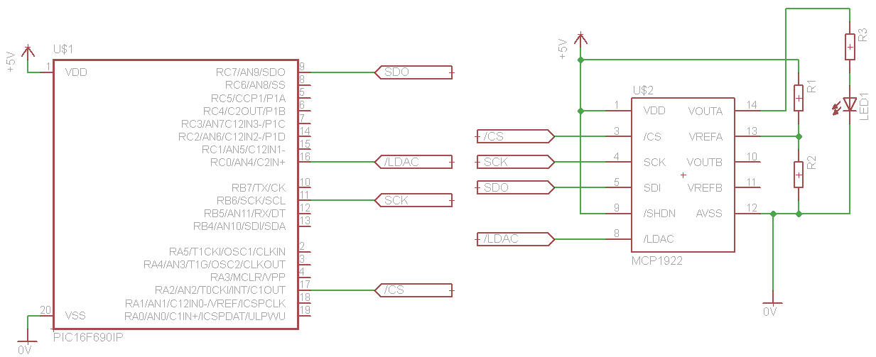
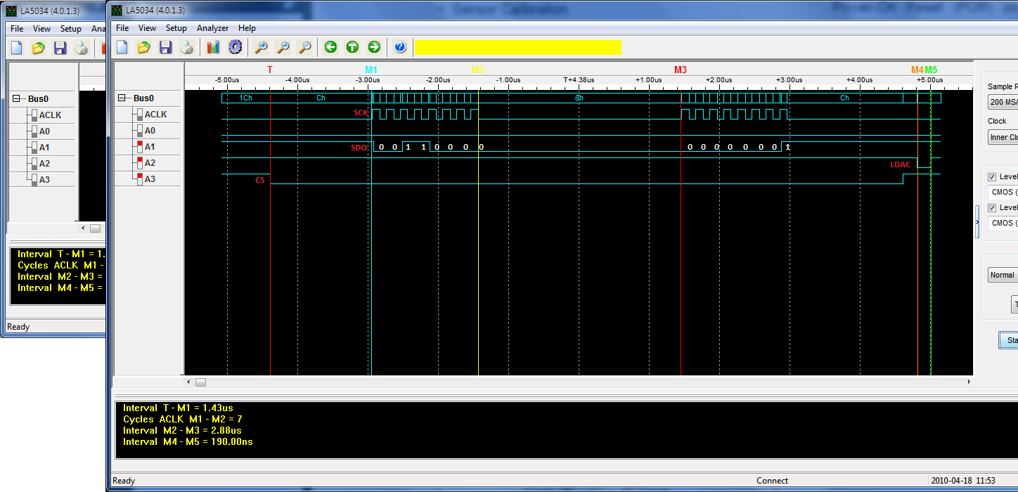
In my first test, I had VREFA connected straight to +5V, When sending a 0x001 to the DAC, the voltage on VOUTA would be +2.4V I've checked the signals with My new Logic analyser and the signals are in-fact correct.
when I change the config settings to have a 2x gain and set the VREFA to +2.5V using a voltage divider. I get nothing on VOUTA no mater what value i set it.
Think you guys could help?
here is the code that I'm using:
sorry for the large images, not sure how to resize them in the post
Update: Bit of a mistake, its a MCP4922 not MCP1922. sorry
Last week I ordered some sample components from Microchip and got them in the mail two days ago.
I got 2 MCP1922 (dual 12 DAC) and 2 24FC512 (64KByte EEPROM)
I'm trying to get the DACs working at the moment but I'm having a few problems.
I've followed the data sheet and set up the circuit accordingly, I'm sure I'm sending the the SPI commands and I'm sure I have the correct voltage levels set up.
In my first test, I had VREFA connected straight to +5V, When sending a 0x001 to the DAC, the voltage on VOUTA would be +2.4V I've checked the signals with My new Logic analyser and the signals are in-fact correct.
when I change the config settings to have a 2x gain and set the VREFA to +2.5V using a voltage divider. I get nothing on VOUTA
no mater what value i set it.Think you guys could help?
here is the code that I'm using:
Code:
int main()
{
	init();
	spi_init();
	int test = 0x01;
	char temp,temp2, conf = 0x00;
	conf = 0b00010000;
	while(1)
	{
		temp = conf | ((test >>8)&0x0F); //first byte is made up of the config bits and the most significant 4 bits of test.

		temp2 = test&0xFF; //the rest of test
		RA2 = 0;//bring CS low
		spi_write(temp);//send first byte
		spi_write(temp2);//send second byte
		RA2 = 1;//bring CS high
		RC1 = 0;//send LDAC low to latch the new value onto the output
		RC1 = 1;//bring it high again.
		test++;//increment the value
		DelayMS(10);
		if(test>4096)//if gone over the max, then resest to 0
			test = 0;

	}
}
sorry for the large images, not sure how to resize them in the post
Attachments
Last edited:
