Continue to Site

Welcome to our site!

Electro Tech is an online community (with over 170,000 members) who enjoy talking about and building electronic circuits, projects and gadgets. To participate you need to register. Registration is free. Click here to register now.

  • Welcome to our site! Electro Tech is an online community (with over 170,000 members) who enjoy talking about and building electronic circuits, projects and gadgets. To participate you need to register. Registration is free. Click here to register now.

Wireless Project

Status
Not open for further replies.

AtomSoft

Well-Known Member
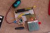
Hey guys i have been going crazy over something that is supposed to be simple... I bought these 2 wireless parts. One Transmitter and One Receiver.

RECEIVER: SparkFun Electronics - RF Link 4800bps Receiver - 315MHz
TRANSMITTER: SparkFun Electronics - RF Link Transmitter - 315MHz

The RECEIVER says data rates UPTO 4800bps so i assume 2400bps is fine. If anything i can alter the code to send at 4800bps and receive at same. If anyone thinks that can be the issue.

Im not sure which side is not working or if both are not. I have placed my code for both below. I checked the BAUD (SPBRG) numbers and they seem to be correct.

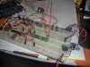
The 18F2525 (TRANSMITTER) is running at 40Mhz
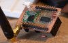
The 18F248 (RECEIVER) is running at 10Mhz

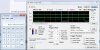
My problem is the receiver is not getting my data and every time i check RCSTA on the RECEIVER i am getting a FRAMING ERROR...

The TRANSMITTER has 2 BUTTONS to send a 0x01 and a 0x02 and a LED to show me when a send is complete.

The Receiver is in DEBUG mode to catch what data is coming.
TRANSMITTER CODE:
Code:
/* *****************************************************************************
;                                                                             *
;    Filename:                     				                              *
;    Date:                                         	                          *
;    File Version: 001                                                        *
;                                                                             *
;    Author:   Jason Lopez                                                    *
;    Company:  AtomSoft                                                       *
;                                                                             *
;***************************************************************************** */

#include <p18f2525.h>
#include <delays.h>
#include <string.h>

#pragma config WDT = OFF, LVP = OFF, OSC = HSPLL

/************************************
Prototypes
*************************************/
void main(void);
void SendUART(unsigned char data);
void init_uart(void);
void delay_ms(int count);

#define BTN1 PORTBbits.RB1
#define BTN2 PORTBbits.RB2
#define LED  LATCbits.LATC3

void main(void){

	ADCON1 = 0x0F;
	TRISB = 0b00000110;
	TRISC = 0x00;
    init_uart();

	while(1){
		if(BTN1){
			LED = 1;
			delay_ms((int)500);
			while(BTN1);
			SendUART(1);
			LED = 0;
		}
		if(BTN2){
			LED = 1;
			delay_ms((int)500);
			while(BTN2);
			SendUART(2);
			LED = 0;
		}
	}
}
//417us bit for 2400bps
void init_uart(void){
    TRISC  = 0b10000000;

    TXSTAbits.SYNC = 0; 
    BAUDCTLbits.BRG16 = 0;
    TXSTAbits.BRGH = 0;
    SPBRG = 255;     //2400bps

    TXSTAbits.TXEN = 1;  //ENABLE TX
	RCSTAbits.CREN = 1;	 //ENABLE RX
    RCSTAbits.SPEN = 1;  //ENABLE SERIAL PORT and PIN Config

    PIR1 = 0x00;
}

void SendUART(unsigned char data){
	while(!TXSTAbits.TRMT);
    TXREG = data;
    PIR1 = 0x00;

}
void delay_ms(int count){
	int x;
	for(x=0;x<count;x++){
		Delay100TCYx(99);
	}
}
RECEIVER CODE:
Code:
/* *****************************************************************************
;                                                                             *
;    Filename:                     				                              *
;    Date:                                         	                          *
;    File Version: 001                                                        *
;                                                                             *
;    Author:   Jason Lopez                                                    *
;    Company:  AtomSoft                                                       *
;                                                                             *
;***************************************************************************** */

#include <p18f248.h>
#include <delays.h>
#include <string.h>

#pragma config WDT = OFF, LVP = OFF, OSC = HS

/************************************
Prototypes
*************************************/
void main(void);
void SendUART(unsigned char data);
unsigned char GetUart(void);
void init_uart(void);
void delay_ms(int count);

void main(void){
	unsigned char data;

	ADCON1 = 0x0F;
	TRISB = 0b00000110;
	TRISC = 0x00;
    init_uart();

	while(1){
		data = 0;
		data = GetUart();
		delay_ms(100);
		if(data)
			Nop();
	}
}

void init_uart(void){
    TRISC  = 0b10000000;

    TXSTAbits.SYNC = 0; 
    TXSTAbits.BRGH = 0;
    SPBRG = 64;     //2400bps

    TXSTAbits.TXEN = 1;  //ENABLE TX
	RCSTAbits.CREN = 1;	 //ENABLE RX
    RCSTAbits.SPEN = 1;  //ENABLE SERIAL PORT and PIN Config

    PIR1 = 0x00;
}

void SendUART(unsigned char data){
	while(!TXSTAbits.TRMT);
    TXREG = data;
    PIR1 = 0x00;

}

unsigned char GetUart(void){
unsigned char temp = 0;

	while(!PIR1bits.RCIF)

	temp = RCREG;

	if(RCSTA & 0b00000110){
		//ERRORS
		RCSTAbits.CREN = 0;
		delay_ms(1);
		RCSTAbits.CREN = 1;
	}

	return temp;
}

void delay_ms(int count){
	int x;
	for(x=0;x<count;x++){
		Delay100TCYx(99);
	}
}
 
Some Results.. i added some power caps and nice thick wire for antenna ... when i press button i get a break point but the data is 0xFF ... no Framing Errors
 
Ok more progress .... i switched to 2 PIC18F2525's

Both 40Mhz ... same speeds of 4800bps

When i press button 1 i get: 0b10000011 then right after i get a 0b00000000
When i press button 2 i get: 0b11000000 then right after i get a 0b00000000

Looks kind of inverted i know... Ill send something easier to tell the difference from..
Like button 1 will now send 0b11100011 (0xE3)
..... button 2 will now send 0b00011100 (0x1C)

UPDATE:
Button 1 Pressed i get a 0x0E (00001110)
Button 2 Pressed i get a 0xE0 (11100000)
 
Last edited:
That is a strange one!
I have used RF transmitters / receivers before, I used a 0.25m antenna cable, coax RG59 type cable or similar will do, 50 ohm rated, worked fine with a "stubby" arial.
The code was 2400bps but worked up to 9600, I used two 16F chips running at 20MHz each, I put the modules a fair distance apart, and I used a radio scanner to see if there was anything transmitting currently on that band, some of the more high end modules allowed for a frequency step up, which you could select between 7 frequencies I think.

Framing errors usually refer to parity, baud rate or logic errors.

Worst case, scope the data to and from the RF moudles and see if you can spot any errors on each path.

Wilksey
 
Going to have to try and use pickit to see what data is going into it. Ill post some images of data when done...

Im using 20 AWG in breadboard as antenna
 
Last edited:
The antenna shouldn't make a difference if using it "local".

In fact, it would probably work without an antenna, the antennas I used went over 1km and still worked (direct line of sight however!).

Interestingly, they worked better outside than inside!
 
Transmit seems to be ok.. cant really test part there but i can see im sending the right data... i tried 01010101 and see this...

The calculator shows that for 4800bps each bit should be 208us... which is correct in PICKIT2...

**broken link removed**
 

Attachments

  • send..jpg
    send..jpg
    218.7 KB · Views: 191
Last edited:
Now here is what im getting from PICKIT2 but using RECEIVER... its a variable speed ...
The Calc shows bps for the selected bit in Analyzer (within pickit 2 software)

LARGE IN: This shows the larger of the 2 bits has a bit rate of 3289bps
**broken link removed**

SMALL IN: This shows the smaller of the 2 bits has a bit rate of 8333bps
**broken link removed**
 

Attachments

  • largeIN..jpg
    largeIN..jpg
    207.8 KB · Views: 195
  • smallIN..jpg
    smallIN..jpg
    213.9 KB · Views: 219
Last edited:
The antenna shouldn't make a difference if using it "local".

In fact, it would probably work without an antenna, the antennas I used went over 1km and still worked (direct line of sight however!).

Interestingly, they worked better outside than inside!

heh ill take a picture of my setup.... and update this post

UPDATE:

100_1391-jpg.39823
 

Attachments

  • 100_1391..jpg
    100_1391..jpg
    370.6 KB · Views: 1,054
Last edited:
These are notoriously tricky.

You should be encoding data for DC balance with these. I know Nigel has a tutorial that gets mentioned all the time with Manchester. When I use these I used a 2byte/3byte encoding method and timers to find the proper sampling points, it worked pretty well, but I ended up stealing code from an Arduino library called VirtualWire that worked better. The code was simple to port to my own compiler/microcontroller and just needed to be hooked to a hardware timer. The code can be googled.

A breadboard is not a good environment for these. They really need to be soldered down and have good power filtering.

These things are not worth it anymore. The headaches getting them working is too high for too little. The receiver itself is $5.95, for $6.95 you can get a RFM12B transmitter/receiver from Sparkfun that's fairly easy to work with, has good range, and has all sorts of nice features like RSSI.
 
I'm pretty happy with the RFM12B and the simple networks I've made up. With the RFM12B you should still use encoding, though. You can get away without it, but speed and reliability are improved with it. If you want the transceiver to do absolutely everything for you, you can get the RFM22B which will do the encoding for you as well, but there's less sample code for it and it's more expensive. 2byte/3byte encoding is pretty simple anyway.
 

Attachments

  • 20091104-rf-node-proto2-001.jpg
    20091104-rf-node-proto2-001.jpg
    191 KB · Views: 415
  • 20090930-lcd7110-thru-pcb-001.jpg
    20090930-lcd7110-thru-pcb-001.jpg
    238.1 KB · Views: 373
ok back to this project... for receiving should i manually receive then? Like i can send out a byte in 2 parts.. where half byte is START NIBBLE and other half is DATA and merge the 2 at my side... like ... to send 0x02 i send 2 bytes

1011-0000 BYTE 1
1011-0010 BYTE 2

Where 1011 would be used to count my data comming in.. then have seperate packets to check if data is mines and etc...
 
Try connecting the PICS together with just a wire, leave the RF modules out. Get them working properly this way to make sure your timing is good. Then add the RF modules and work from there.
 
Just tried and it works 100% wired... wireless not so... im trying to send a 'J' and a 'a' so i can see the letters in MPLAB... but i just get a 1 or 0 when i press the buttons
 
As I've said repeatedly, the hardware UART isn't suited to wireless - you can't just send basic 8N1 type data. Even worse, the polarity is the wrong way roud, if you want to use the UART (even though it's poor anyway), then you need to add hardware inverters at each end.
 
Nigel i have tried to send out 8 bit data at 4800bps through software and no good... The info i have read everywhere stated this sucker takes in a byte and sends out a byte... i dont care for encoding anything right now. Just want data in and out... if i cant get that working then everything else wont matter. and i wont waste time with it...

These things are a huge hassle... I have to learn to read comments before buying things. lol

Go and read my tutorial, which explains why it's not working, and why you use Manchester coding - you can't just send data in and out from a UART, it's the wrong polarity.

Or if you use a software UART you 'can' send serial data, as long as you invert it in the software - but it's still a poor and unreliable system, but at least it works.
 
Status
Not open for further replies.

Latest threads

New Articles From Microcontroller Tips

Back
Top