Continue to Site

Welcome to our site!

Electro Tech is an online community (with over 170,000 members) who enjoy talking about and building electronic circuits, projects and gadgets. To participate you need to register. Registration is free. Click here to register now.

  • Welcome to our site! Electro Tech is an online community (with over 170,000 members) who enjoy talking about and building electronic circuits, projects and gadgets. To participate you need to register. Registration is free. Click here to register now.

Wireless Headphone External Mic

NBD925

New Member
Hello I have a set of Konnect Adventure Bluetooth Headphones.

Link Below:

https://a.co/d/ccptfDW

The Microphone on these sits in the left earpiece and is muffled when you speak into it. I imagaine because your ears are covering it. I would like to wire in something like a Boom mic or remote microphone that I can stick in my helmet closer to my mouth.

Example: solder in the extension mic leads with the existing connection or replace the the old mic with the new extension. The wires would push through the existing mic hole and extend out to the front chin area of my helmet where the Mic would be secured with small velcro.

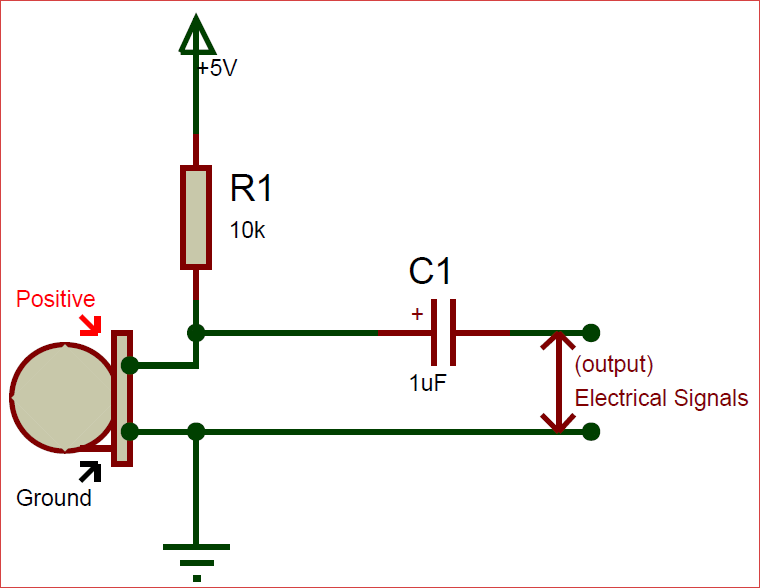
Here are some pictures of the connections inside the headphone. I see 4 wires soldered on but it looks like only 3 are actually connected. Why 3 wires? Power, Ground, Signal???

E7276FF6-BD2A-4BE8-BD9F-8D6A1DDF6AA3.jpeg
AE014DA0-A65D-4F91-9068-DDC2520CAB0A.jpeg
 
Are both the outer ones grounds? A picture of the back of the PCB would be helpful?

If you touch something metallic to each contact in turn while listening to the audio, you should hear a click or buzz when you touch an analog audio connection?

It looks like a MEMS mic; they can have either analog or digital output.
 
I will work on getting a picture of the back side of this board.

It looks like this is an Analog MEMS Mic. I found a picture of an analog Mems Mic wiring diagram and it looks about right.
9B07529F-DFEC-4718-B5F5-438F8E95B99A.png

E25EE9B1-1438-4EDF-B552-EBD1BA9FA86E.jpeg
 
Last edited:
Would I be able to just solder in a Regular microphone into the connections.
Not quite directly, as an electret mic capsule needs a bias feed and the output on the same terminal.

However until the connections are identified, it's guesswork as to where to connect it..

Circuit-using-Electret-Condenser-Microphone.png
 
With a 5V supply and a 10k biasing resistor, many electret mics will not work properly.
Most electret mics use a 2V minimum supply and draw 0.5mA max. Then the electret mic gets 5V - (10k x 0.5mA)= 0V.
Using a 4.7k resistor with the 5V supply, the mic gets 2.65V and works fine.

I use a 10k resistor with a 9V supply.
Its kind of a moot point considering that we don't know the voltage. 2.5K to 5K is the normal range for electret mics. The computer mic input circuit uses the 2.5K with 5V internally, So there is a lot of people don't know the support circuit is already installed. The only thing with some sound cards, you have to turn on the 5V in the microphone's control panel in the computer's sound card settings .

To the TS, yes you could use a different mic, its just that you may have to add a support circuit to it.
 

Latest threads

New Articles From Microcontroller Tips

Back
Top