Continue to Site

Welcome to our site!

Electro Tech is an online community (with over 170,000 members) who enjoy talking about and building electronic circuits, projects and gadgets. To participate you need to register. Registration is free. Click here to register now.

  • Welcome to our site! Electro Tech is an online community (with over 170,000 members) who enjoy talking about and building electronic circuits, projects and gadgets. To participate you need to register. Registration is free. Click here to register now.

Why Opamp with potentiometer?

Status
Not open for further replies.
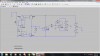
I am going to use a regular solderless breadboard. when I built the upper section on breadboard the circuit configuration was a little bit different. there was no buffer between first stage and the last one. besides configuration of last stage was different. Resistor at the output of current mirror wasn't connected to the ground and Non inverting pin of last op amp was grounded. In this kind of configuration, circuit began oscillating. I add the buffer when I assemble it again but should I keep non inverting pin of the last op amp grounded or not?
 
Last edited:
Hi,

What do you mean by "keep the non inverting pin of the last op amp grounded" ?
The last op amp is the differential amp with resistors pairs 10k and 100k, right? You cant ground the non inverting terminal or it wont function right anymore. Unless you mean something else.
 
Yes, that's right. But I want to assemble only the upper section of this circuit. for doing this, I build the first stage as it is in the main circuit then I add the buffer(the second op amp). but for the last op amp I don't know what should I do with the 100k and 10k resistors which are connected to the non inverting pin of op amp. one side of 10k resistor is connected to the buffer of lower section while I don't want to assemble the lower section right now. Simply put, what is the configuration of last op amp when I only want to build the upper section and test it? I think I should change this part a little bit because I don't have the lower section (lower current mirror and buffer).
 
Hi,

Oh you mean the last stage without the lower section. Ok i understand you better now.

In that case just ground the 10k resistor that normally connects to the lower section output buffer. You'll still have the 10k and 100k pairs. It may work to just ground the non inverting terminal, but i'd go with the two resistors and that way you'll be ready for the lower section once the upper section is fully tested.

BTW i should clarify something. The slew rate increase we talked about earlier does in fact increase with the two current mirrors, but there may be a drawback to using just an op amp for the output stage. I'm currently still looking into this.
If we used a pair of current mirrors on the output stage too with another buffer then we might get away with more, like a higher output voltage peak as well as a bandwidth increase.

Here are some notes that apply when usinn the LM358. Note that we are not really limited to this particular op amp, but just for example i used the specs for this op amp because we are using that model and everything scales to other op amps anyway.

Specs:
Gain bandwidth product (GBP): 1000000Hz
Slew rate: 500000 v/s

Slew rate limited max bandwidth, 1v peak output: 80kHz
Slew rate limited max bandwidth, 0.1v peak output: 800kHz

Bandwidth limit due to GBP, any output, gain of 1: 1Mhz
Bandwidth limit due to GBP, any output, gain of 10: 100kHz

We have to make sure that the slew rate limit AND the bandwidth limit are both satisfied in order to create a real workable circuit, so for example in order to see an 80kHz bandwidth we'd have to keep the max output to 1v peak and max gain of 10, and to see an 800kHz bandwidth we'd have to keep the max output to 0.1v peak and a max gain of 1.
 
Last edited:
The bandwidth you talked about is related to LM358 op amp or not? I mean when I use op amp TLo81 can I get a better max bandwidth? I agree with you that having a max bandwidth is an important issue but having a relatively good gain is crucial too. If we increase the bandwidth and on the other hand we get a unity gain from the entire circuit(assuming input voltage= 1v). In this case circuit acts like a buffer.
 
Hi again,

No that's just for the last stage. We can get the gain from the current mirrors remember?
We may want more gain, but we'd have to look at the individual case by case.

Yes, i believe the TL081 has a much higher bandwidth and also faster slew rate, so we'll definitely see improvements there.
Roughly speaking, if the op amp of choice has a bandwidth X times higher than the LM358, then we can get X times the bandwidth out of the entire circuit using the better op amp. If the GBP is 3Mhz for example, that means we can get 3 times the bandwidth (or more) from the new op amp choice.

Also note that i had to edit my previous post extensively so you may want to re-read that one.
 
Hi,


BTW i should clarify something. The slew rate increase we talked about earlier does in fact increase with the two current mirrors, but there may be a drawback to using just an op amp for the output stage. I'm currently still looking into this.
If we used a pair of current mirrors on the output stage too with another buffer then we might get away with more, like a higher output voltage peak as well as a bandwidth increase.

I don't understand one thing. You want to add two more current mirrors on the output stage, right? first of all I have to detect what causes oscillation. Maybe it's because of using current mirrors. Although I use transistor arrays instead of discreet transistors it's still likely to have the issue of unmatching transistors. By adding one or 2 current mirrors this kind of problem becomes twice, doesn't it?
 
Last edited:
I decide not to use any potentiometer for building upper section of this circuit but when I input Ac voltage and measure the output I may have some offset voltage at the output . one of questions that I have thought about a lot is, would it be necessary to decrease offset voltage to zero? should we always do it or it depends on the range of offset voltage?
 
Hi,

First get the one section working, then we proceed with anything else like more current mirrors, if you really need them that is.

The offset only has to be adjusted if your application needs a low offset. Many apps dont need that so a little is ok for those.
 
I am going to use LM358 for building the upper section. In LM358 datasheet pin number 4 is VEE/ GND. I have to bias my op amp with +15 and -15 vdc. can i apply -15 v to pin number 4 and 15v to pin number 8. LM358 is a dual op amp I don't know how can I use only one of op amps from this package. :-(
 

Attachments

  • Untitled.png
    Untitled.png
    11.5 KB · Views: 156
The LM358 has a maximum allowed supply of +16V and -16V so using a supply as high as +15V and -15V might reduce the life of your circuit. The opamp will work fine with much lower supply voltages. Notice that we call it the power supply voltages and not bias voltages. Bias voltages are used at the input of an opamp or transistor, not at its power supply pins.

The LM358 is very old and is probably the first low power dual opamp ever made with the LM324 the first low power quad opamp ever made (their circuits are identical). First a single opamp was produced but I do not know its part number and I do not know if it is still made.

It is easy to disable one of its opamps. I would connect its inverting input to its output to make it a follower then connect its non-inverting input to 0V.
 
It is easy to disable one of its opamps. I would connect its inverting input to its output to make it a follower then connect its non-inverting input to 0V.

So I can connect pin number 4 which is shown as VEE/ GND to negative supply voltage, right?
 
Hi,

Yes that sounds right.

I dont see a problem with doing plus and minus 15 volts but you can ask AudioGuru why he thinks it's not a good idea. They seem to be spec'ing it at plus and minus 16 and they note that it accepts a wide range of supply voltage levels.
 
I want to see the offset voltage at the output of circuit which is attached to the post. This circuit is the upper section of the entire circuit. I didn't apply any signal to non-inverting terminal of the first op amp in order to measure the offset of the very last op amp. But I don't know what causes this kind of peak (3.6v) at 0.1ms?
 

Attachments

  • Untitled.png
    Untitled.png
    121.4 KB · Views: 142
  • Untitled1.png
    Untitled1.png
    121.6 KB · Views: 140
Last edited:
Hi,

It's better not to use the 741 op amp as that has other problem which you dont want to have to deal with now.

What node are you looking at with that scope pic?

Try to post the asc file when you can.
 
As I simulate the circuit with LM358 it would be better to use it. But I should disable one of the op amps out of 2 because LM358 is a dual op amp. In fact I have to use more wires for LM358 than UA741 due to disabling one of op amps in the package. That's why I prefer to use 741 but I have no clue what's the problem of using that.

LM358 has no terminal for potentiometer. Op amps like Tlo81 and 741 have offset null terminals for connecting potentiometer. Then how can we regulate the DC offset voltage without potentiometer?
 
Last edited:
The 741 input common mode voltage range is not as good as the LM358. So if you use the 741 you'll have to make sureyou limit the input to 3v above the minus supply and 3v below the positive supply voltage.

If you intend to adjust the DC offset then you need something to adjust. That's where the pot comes in.

It is all too simple to wire the LM358 to work as a non inverting buffer. One wire from input to output, one wire to ground.
 
The 741 input common mode voltage range is not as good as the LM358. So if you use the 741 you'll have to make sureyou limit the input to 3v above the minus supply and 3v below the positive supply voltage.

If you intend to adjust the DC offset then you need something to adjust. That's where the pot comes in.

You mean I can adjust the DC offset voltage of LM358 with potentiometer? I don't know how to connect it because there is no offset null terminal.
 
Status
Not open for further replies.

Latest threads

New Articles From Microcontroller Tips

Back
Top